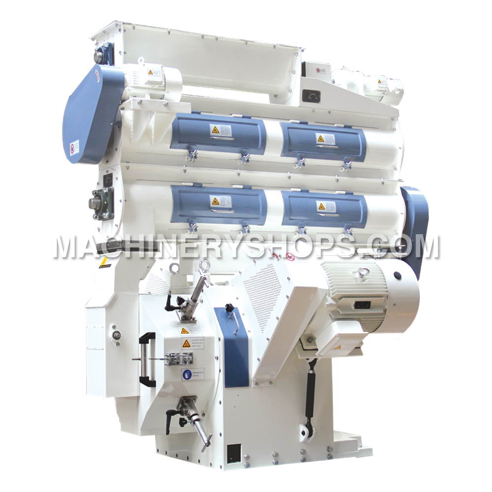
The pellet mill is directly driven by timing belt, which is characterized by its ideal drive ratio, great driving moment, smooth rotation, high throughput, low noise, easy operation and maintenance.
This type of pelleting machine can be fitted with many kinds of ring dies with φ1.5~φ12 die holes and different thickness, and the user can select based on self demand for achieving the optimum technical and economic efficiency.
This machine, characterized by its stable running performance, high throughput and high pellet forming ratio, is applicable for producing pellet feeds for livestock and poultry.
The adjustable speed control motor is adopted for feeding of this machine, and the machine is equipped with an overload protection device and an outside discharging mechanism, and the bypass gate can be opened automatically in case of overload of the main motor.
Different type of conditioners are optional as required, such as single-, double- and triple-pass conditioners as well as a double-shaft differential conditioner.
This pelleting machine is specially used for animal feed processing, generally for processing powdery, flowable and easily pelletized materials to produce pellet feeds for livestock and poultry.
Do not use it for processing food.
To ensure safety and efficiency, this machine shall be used in the areas with an altitude lower than 1000 m, a temperature from -5℃ to 40℃ and an air relative humidity from 30% to 95%.
If the area does not conform to above conditions, please indicate specially when ordering.
Thursday, October 30, 2014
Friday, September 19, 2014
The Usage on Muyang TLMC12 Jet Filter Dust Collector
Dust concentration of dust-containing air, relative humidity, physical and chemical characters of dust such as dust size, density, adhesivity and explosive repose angle shall be known after determining to use the filtering sleeve dust collector.
Consider the filtering air speed and filtering area when selecting a dust collector. The designed filtering air speed of full series dust collectors shall be not more than 4 m/min. The filtering air speed is determined by dust characteristics and density, usually the middle/lower limit is selected; as for light and small dust particles, the filtering air speed shall be much lower, or even less than 2 m/min; the lower the filtering air speed, the higher the dust removal efficiency, however, the cost will be increased; therefore, it is important to select the filtering air speed applicable for the character of dust to obtain a better performance-price ratio. Determine the filtering area based on volume of air to be treated after determining the filtering air speed; see Table 1 for corresponding parameters to select correct dust collector model.
Normally, the feed machine is used for treating dust-containing air with a dust particle size more than 1μm; for treating dust-containing air with a dust particle size less than 1μm, please inform us when ordering, so that we can select other filter material and guide you to adjust the corresponding working parameters.
Please inform us when ordering if the dust collector will be used for central dust collecting and pneumatic conveying and the air pressure exceeds 15000Pa, so that we can adjust the corresponding structure.
It is recommended to select a dust collector with larger size or equip an additional pre-purifier when the dust concentration at the entry of the dust collector is more than 15g/m3.
Please inform us if you have any special requirements to the dust collector or you have any other ideas.
In addition, we have other feed machinery available here, you can contact anytime.
Consider the filtering air speed and filtering area when selecting a dust collector. The designed filtering air speed of full series dust collectors shall be not more than 4 m/min. The filtering air speed is determined by dust characteristics and density, usually the middle/lower limit is selected; as for light and small dust particles, the filtering air speed shall be much lower, or even less than 2 m/min; the lower the filtering air speed, the higher the dust removal efficiency, however, the cost will be increased; therefore, it is important to select the filtering air speed applicable for the character of dust to obtain a better performance-price ratio. Determine the filtering area based on volume of air to be treated after determining the filtering air speed; see Table 1 for corresponding parameters to select correct dust collector model.
Normally, the feed machine is used for treating dust-containing air with a dust particle size more than 1μm; for treating dust-containing air with a dust particle size less than 1μm, please inform us when ordering, so that we can select other filter material and guide you to adjust the corresponding working parameters.
Please inform us when ordering if the dust collector will be used for central dust collecting and pneumatic conveying and the air pressure exceeds 15000Pa, so that we can adjust the corresponding structure.
It is recommended to select a dust collector with larger size or equip an additional pre-purifier when the dust concentration at the entry of the dust collector is more than 15g/m3.
Please inform us if you have any special requirements to the dust collector or you have any other ideas.
In addition, we have other feed machinery available here, you can contact anytime.
Tuesday, August 26, 2014
Hammer Tip: Go High Speed to Control Particle Size
In most cases, feed manufacturers primarily rate a hammermill's performance on its capacity to grind a certain amount of material in a given time. However, this practice ignores particle size, an important consideration in handling characteristics, pellet durability and animal performance. Traditionally, feed manufacturers who use hammermills to grind grains and other materials control particle size by changing the size of the hammermill screen holes. While screen size has a major influence on particle size, hammer tip speed is also an important factor. Generally, if all other factors are the same, hammermills with higher hammer tip speeds produce a finer grind than those with lower tip speeds.
To understand how tip speed affects particle size, it is important to know how a feed machine operates.
A hammermill grinds by two distinct forces. The first force is impact. As the grain drops into the grinding chamber, it is struck by fast moving hammers and accelerated toward the screen where a second impact occurs.
The particles that don't discharge through the screen immediately form a fluidized bed against the inside of the screen where they are ground by attrition, the second grinding force. With attrition, particles are ground as they are forced against the screen and against each other. Of the two grinding forces, impact is more efficient. Feed machinery manufacturers, therefore, have gone to great lengths to increase the amount of impact that occurs in the hammermill, resulting in steady improvements in grinding efficiency.
One way to increase the amount of impact between hammer and particle is to increase the tip speed of the hammers.
According to basic principles of physics, if motor speed is fixed, increasing the diameter of the rotor will increase the speed of the hammer tip.
Special design and material modifications are required to produce a machine that operates safely at rotation speeds of more than 25,000 feet per minute. The rotor shaft and plates are manufactured from materials that withstand tremendous forces. The assembly is balanced to prevent excessive vibration. Engineers and designers must also give consideration to the bearing mounts, hammermill base and frame to maintain proper alignment and support for the heavy rotor assembly. A hammermill with a higher tip speed will produce a finer grind than one with a slower tip speed, provided the two grinders have the same size screen. If a high-speed hammermill is equipped with a larger hole screen, ground material particle size will be the same for both machines.
To understand how tip speed affects particle size, it is important to know how a feed machine operates.
A hammermill grinds by two distinct forces. The first force is impact. As the grain drops into the grinding chamber, it is struck by fast moving hammers and accelerated toward the screen where a second impact occurs.
The particles that don't discharge through the screen immediately form a fluidized bed against the inside of the screen where they are ground by attrition, the second grinding force. With attrition, particles are ground as they are forced against the screen and against each other. Of the two grinding forces, impact is more efficient. Feed machinery manufacturers, therefore, have gone to great lengths to increase the amount of impact that occurs in the hammermill, resulting in steady improvements in grinding efficiency.
One way to increase the amount of impact between hammer and particle is to increase the tip speed of the hammers.
According to basic principles of physics, if motor speed is fixed, increasing the diameter of the rotor will increase the speed of the hammer tip.
Special design and material modifications are required to produce a machine that operates safely at rotation speeds of more than 25,000 feet per minute. The rotor shaft and plates are manufactured from materials that withstand tremendous forces. The assembly is balanced to prevent excessive vibration. Engineers and designers must also give consideration to the bearing mounts, hammermill base and frame to maintain proper alignment and support for the heavy rotor assembly. A hammermill with a higher tip speed will produce a finer grind than one with a slower tip speed, provided the two grinders have the same size screen. If a high-speed hammermill is equipped with a larger hole screen, ground material particle size will be the same for both machines.
Wednesday, August 20, 2014
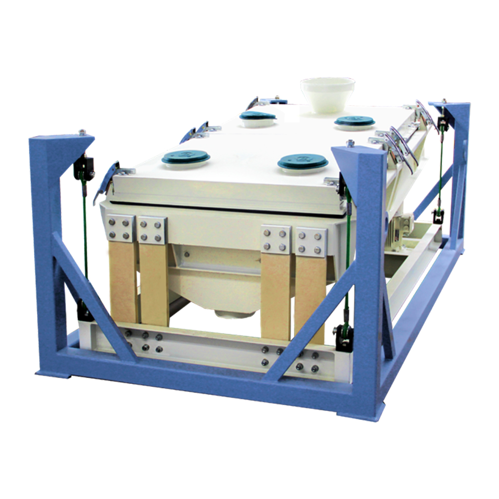
Installation of the Sifter
There are two ways to install Muyang SFJH series Rota-shake Sifters: support base type and suspension type. For support base type installation, the stander of the sifter is directly installed on foundation throught anchor bolts, while suspension type installation is without stander and hanging mechanism, the carrier of the sifter can be directly suspended on the roof of the factory building throught wire ropes; however, there are certain requirements to the installation site and the factory building.
This feed machine leaves the factory as a whole and usually applies support base type installation. Before installation, check against the dimensions in the sample diagram of equipment for enough space, especially the space for operation, maintenance and accessory replacement. To ensure the stability of stationariness, installation site of the sifter shall be solid and horizontal. Meanwhile, material weight in the sifter shall be considered in calculation. The base of sifter shall be connected with the foundation through anchor bolts tightly to prevent the sifter from offset during running.
If suspension installation is applied, it is suggested to assemble the four wire ropes with turnbuckles so as to level the carrier of the sifter. Meanwhile, protection device must be used to protect the sifter when any of the wire ropes is broken.
This feed machine leaves the factory as a whole and usually applies support base type installation. Before installation, check against the dimensions in the sample diagram of equipment for enough space, especially the space for operation, maintenance and accessory replacement. To ensure the stability of stationariness, installation site of the sifter shall be solid and horizontal. Meanwhile, material weight in the sifter shall be considered in calculation. The base of sifter shall be connected with the foundation through anchor bolts tightly to prevent the sifter from offset during running.
If suspension installation is applied, it is suggested to assemble the four wire ropes with turnbuckles so as to level the carrier of the sifter. Meanwhile, protection device must be used to protect the sifter when any of the wire ropes is broken.
Friday, August 8, 2014
SYPZ Type Vacuum Coating System
SYPZ type vacuum coating system is arranged behind pelleting and extruding, and suitable for pellets to be coated with the liquids in large proportion like oil, enzyme preparation, vitamin, antioxidant and amino acid etc. It is also applicable for the pellets with high density, of which the coating rate is low but the coating effect is not good for common pellet surface.
A vacuum liquid coater of the SYPZ series is automatically controlled by a computer with a few operating parameters. It is only necessary to input the output-to-oil ratio, the system will run automatically, so the operation is very convenient. The coater features high accuracy of coating proportion and capacity, and with excellent coating evenness. And the feed machine is characterized by its favorable vacuum degree and vacuum retention.
The sprayed liquid will be fully absorbed under the vacuum condition.
The spraying ratio can reach more than 35 percent.
The spraying accuracy can reach 3 millesimal.
With automatic control system, easy to operate and maintain.
Widely used for spraying the liquid and oil to the extrusion feed and pellet feed.
A vacuum liquid coater of the SYPZ series is automatically controlled by a computer with a few operating parameters. It is only necessary to input the output-to-oil ratio, the system will run automatically, so the operation is very convenient. The coater features high accuracy of coating proportion and capacity, and with excellent coating evenness. And the feed machine is characterized by its favorable vacuum degree and vacuum retention.
The sprayed liquid will be fully absorbed under the vacuum condition.
The spraying ratio can reach more than 35 percent.
The spraying accuracy can reach 3 millesimal.
With automatic control system, easy to operate and maintain.
Widely used for spraying the liquid and oil to the extrusion feed and pellet feed.
Wednesday, July 30, 2014
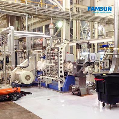
FAMSUN Dry Petfoods Factory Project
--Helping pets live longer, healthier lives through sound nutrition
The trends of humanization of pets, however, has put the flavor, color and shape of petfoods even the aesthetic quality of package in the most important position of pet owner's consumption decision. To be competitive in the high-end market, petfood manufacturer must make its products distinguished.
As a professional and experienced technical supplier, FAMSUN is well prepared to work with pet feed machinery manufacturers to developed their own high-value, nutritional, attractive petfood products. FAMSUN innovative extrusion system and post treatment processes, state-of-the-art processing techniques, as well as customized solutions enable customers to produce various high-end competitive products their own.
Friday, July 25, 2014
Pelletizing Process on Pellet Mill
Startup a new pellet mill or a pellet mill with a new ring die according to following steps:
1) Open the bypass gate;
2) Startup the main motors of the pellet mill. The motor shall be started up in Y firstly, and runs in delta connection while under normal operation speed;
3) Feed a certain amount of oily coarse mash to the inlet of the feed machine manually, and continue feeding until pellet is formed. This is the primary lubrication for the ring die before normal production;
Oil bearing material: generally, feed mash with ≥10% oil content. The raw materials of rice bran, expanding soybean and others can also used as oil bearing material. As for bad quality ring die with rough hole wall, about 15% spun yarn passing through 40 mesh screen can be added in oil bearing material for rinsing and grinding the die (generally persist for more than 30 minutes), otherwise, the materials cannot be discharged.
4) Startup the conditioner motor;
5) Startup the feeder motor, adjust the frequency converter to a low frequency (generally about 5Hz) and allow the feed to enter the conditioner slowly, Do not add any steam at the beginning of pelletizing, close the bypass gate and slowly quicken the feeding speed based on the current of the main motor;
6) Open the steam valve a bit, then increase the feeding amount when the ammeter’s pointer is falling; when the ammeter’s pointer of the main motor reaches the normal load, add steam amount to allow the ammeter’s pointer to fall back. Repeat again and again until the maximum output and the best quality of pellet are obtained under the rated load;
7) A schematic diagram of pellet extrusion is shown in Fig 4.1. The feeding amount and steam supply are different upon the types of ring die and formulas, and the pellet quality varies as well. So the operator shall be rich in operating experience.
1) Open the bypass gate;
2) Startup the main motors of the pellet mill. The motor shall be started up in Y firstly, and runs in delta connection while under normal operation speed;
3) Feed a certain amount of oily coarse mash to the inlet of the feed machine manually, and continue feeding until pellet is formed. This is the primary lubrication for the ring die before normal production;
Oil bearing material: generally, feed mash with ≥10% oil content. The raw materials of rice bran, expanding soybean and others can also used as oil bearing material. As for bad quality ring die with rough hole wall, about 15% spun yarn passing through 40 mesh screen can be added in oil bearing material for rinsing and grinding the die (generally persist for more than 30 minutes), otherwise, the materials cannot be discharged.
4) Startup the conditioner motor;
5) Startup the feeder motor, adjust the frequency converter to a low frequency (generally about 5Hz) and allow the feed to enter the conditioner slowly, Do not add any steam at the beginning of pelletizing, close the bypass gate and slowly quicken the feeding speed based on the current of the main motor;
6) Open the steam valve a bit, then increase the feeding amount when the ammeter’s pointer is falling; when the ammeter’s pointer of the main motor reaches the normal load, add steam amount to allow the ammeter’s pointer to fall back. Repeat again and again until the maximum output and the best quality of pellet are obtained under the rated load;
7) A schematic diagram of pellet extrusion is shown in Fig 4.1. The feeding amount and steam supply are different upon the types of ring die and formulas, and the pellet quality varies as well. So the operator shall be rich in operating experience.
Subscribe to:
Posts (Atom)