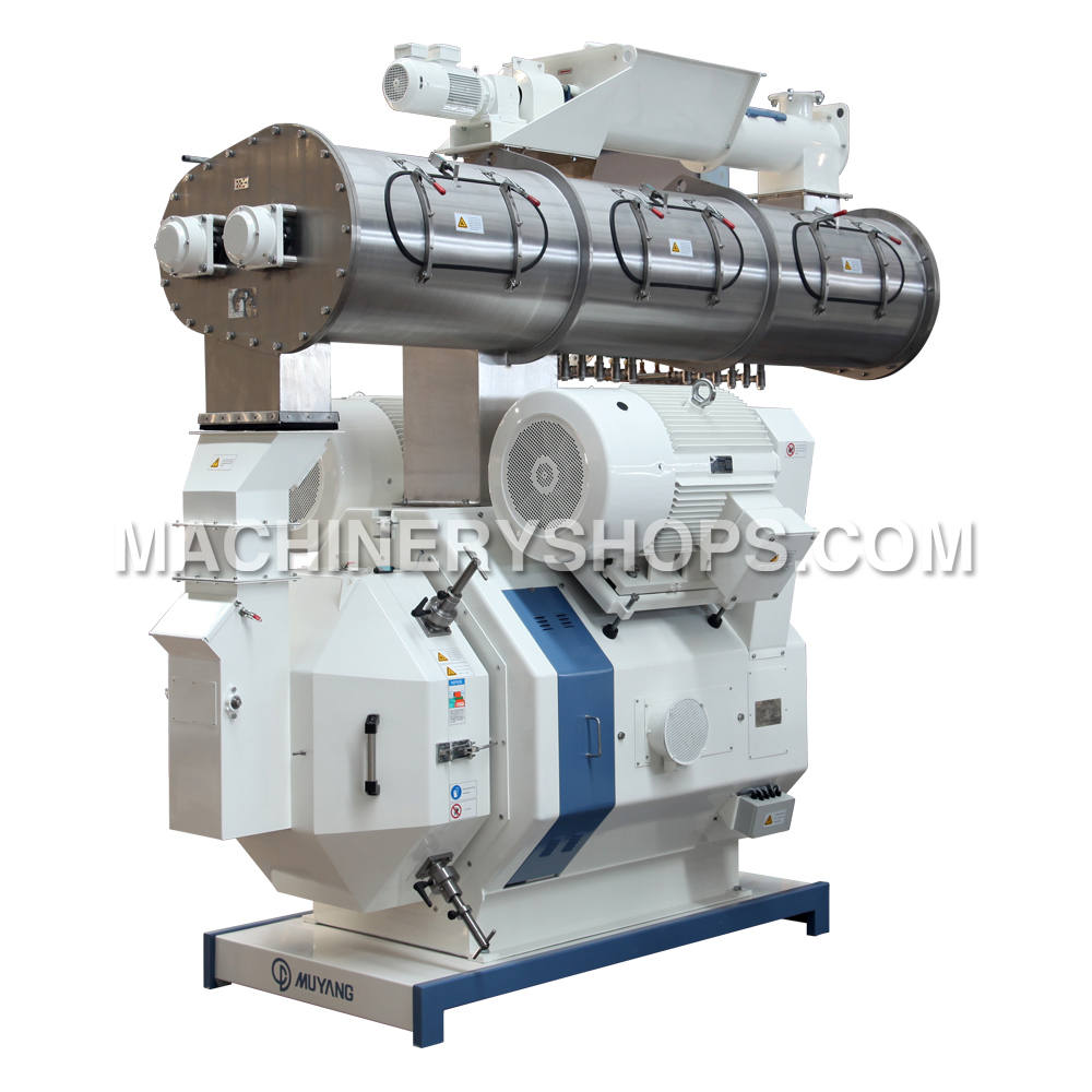
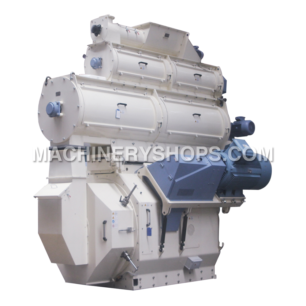
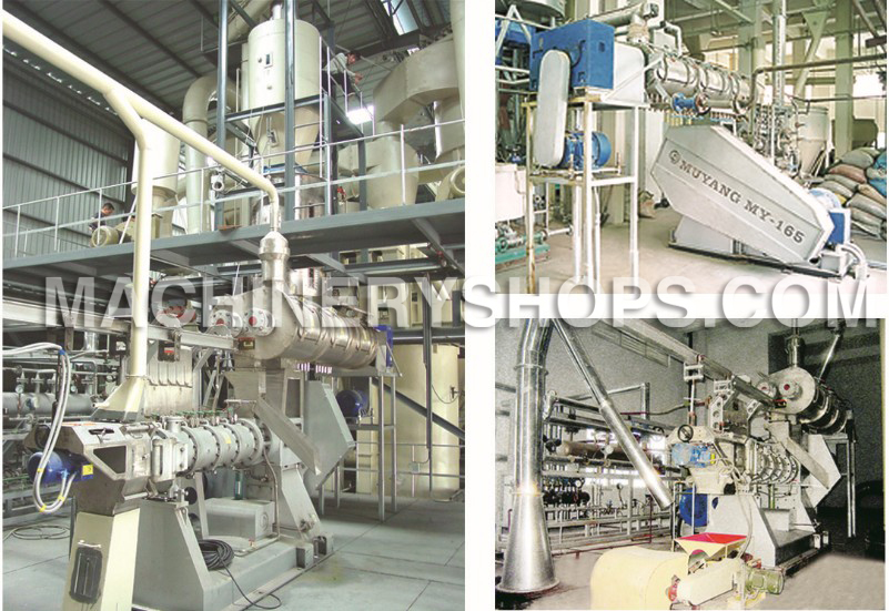
Even Muyang's extruder can solve all your matters, but you should still know what should be done when you face different materials in extruding. Generally, you may choose two materials with both soybean and powdery feed. Following is two ways for extruding:
Operation of soybean extrusion
Main process: preheat → install discharging chamber → adjust discharging screw plug → start the main motor → install the protective hood (without water add device → start feed motor, set the feeding frequency at about 10~12HZ, raise the feed rate gradually after the main motor current is decreased to ensure the stable and continuous producing.
Explanation:
——Screw down the screw plug by use of special wrench, loosen back for 3~4 circles;
——Screw down the screw upper the discharging chamber, fix the discharging screw plug;
——Start the main motor and feeding device of the extruding machine, increase feeding gradually, then install the protective hood;
——Replace the screw plug with different aperture(Φ 8, Φ 10) and adjust the position of discharging screw plug so as to get the different soybean flour output;
——The operation above mentioned should be done quickly to ensure the preheat effect.
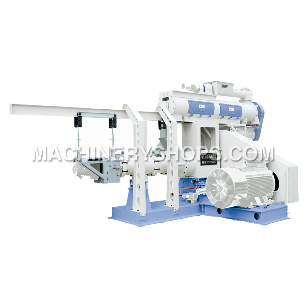
Main controls parameters under normal running (for reference)
Current of main motor 95~100A
Temperature at the discharging part 125~135℃
Operation of powdery feed extrusion
Main process: preheat → install cutting device → start main motor → start feeding device → start cutting device → adjust feeding device to normal operation state → install protective hood
Explanation:
——Fix the machine frame to avoid forward and backward movement after install the cutting device;
——Install different die and adjust cutting speed to get the material in different length and size;
——The add water volume can be set before Preheat.
Main controls parameters under normal running (for reference)
Current of main motor 90~100A
Temperature at the discharging part 110~125℃
Water pressure (select) 0.20~0.35Mpa
It is necessary to know how to operate the extruding machines, and it is also important to manage how to operate for shutdown. Close the water inlet valve first and stop feeding, and then stop the cutting device and principal machine. Remove the discharging device immediately after shutdown, clean the discharging device, after that restart the main motor, add a certain amount of soybean flour to clean away the rest material in the extruding chamber and lubricate it, so as to facilitate the next startup.
Wednesday, September 25, 2013
Tuesday, September 24, 2013
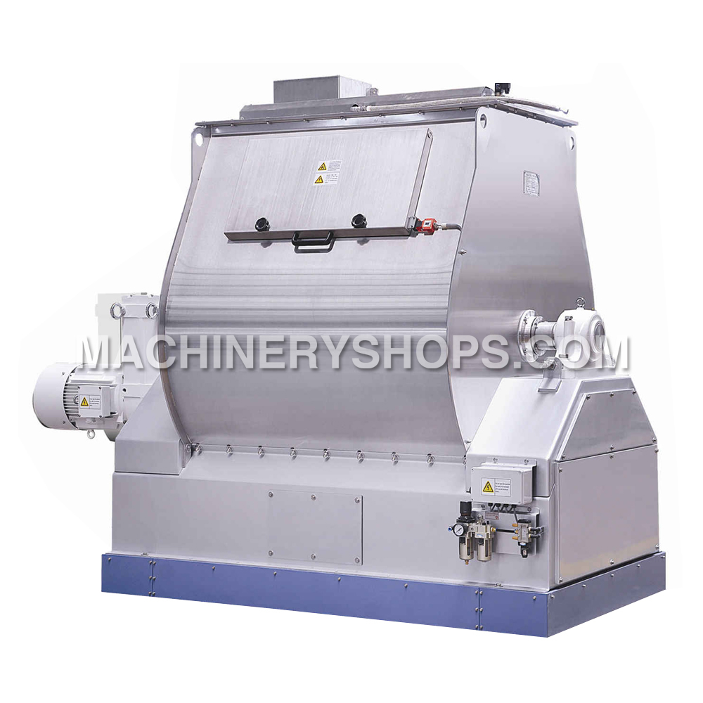
Spare Parts on SJHS2A Double-circle Paddle Mixer
Our works is responsible for repairing or replacing parts (exclusive wearing parts) which are faulted due to manufacturing quality within one year from the date of leaving the factory under normal use and safekeeping by the customer, excluding the operations not in accordance with the operating instructions and human factor.
Our works continues to undertake maintenance and repair on the mixing machines after one year from the date of leaving the factory, to ensure normal use of the customer, but the expenses shall be borne by the customer.
Some parts and components in this mixing machinery are worn off gradually when in use. If these parts are still used after worn to a certain degree, the property of equipment will be affected and dangerous accidents will occur probably. Therefore, these parts and components shall be replaced timely after used for a certain period. The spare parts in this Operation Manual is also called wearing parts.
Whether the spare parts can be ordered timely and accurately will influence your production. So in order to purchase right spare parts, when place an order, please mention the corresponding serial number, code, description of the spare part and the quantity needed in the order list (see Section 7.3 Ordering list of spare parts). And provide us the order list via mailing or e-mail; if possible, please attach a sketch of the spare parts you require.
Sunday, September 22, 2013
Main Structure on MUZL 610TW Type Pellet Mill
MUZL 610TW Type Pellet Mill mainly consists of a feeder, a conditioner and a principal machine of pellet mill (mainly including two main motors, an assembly of rotor, a ring die, press rollers, two assembly of cutting knives, a lifting device for the ring die and a lubrication system) (Fig 2.1).
1. Feeder
2. Conditioner
3. Lifting beam
4. Magnet
5. Assembly of cutting knife
6. Main motor
7. Shear pin
8. Lubricating system
9. Ring die
10. Roller
11. Scraper
The working procedure is shown as follows:
The mixed mash enters the feeding auger from the pelletizing chamber in a proper feeding amount through adjusting the rotating speed of the frequency control motor, and then enters the conditioner. The material will be sufficiently mixed with steam in the conditioner by stirring paddles of the conditioner, and molasses or oil can be added through the feeding inlet for molasses if necessary. The temperature of conditioned compound mash is normally controlled within 65~95℃ and the humidity 14~18% based on different formulas, and finally the material enters the pelletizing chamber and is pelletized to pellets by the press rollers and the ring die.
Feeder
The feeder on the pelleting machine is composed of a frequency control motor, a speed reducer, a sprocket driving device, an auger shaft and auger housing.
The frequency variable speed control motor is composed of a frequency conversion motor and a speed reducer. Working with the frequency converter, output rotating speed of the motor can be changed. (See Operation Manual of Speed Control Motor and Operation Manual of Frequency Converter for details).
A cycloid pin gear speed reducer with a speed reducing ratio of 1:17 allows the feeding auger to regulate speed in a range of 0~100 r/min.
Conditioner
A common conditioner is composed of a motor, a main shaft, paddles, a case, a steam inlet and the molasses inlet.
The conditioner case is made of stainless steel and the paddles are made of high alloy wear resistant material or stainless steel.
The conditioner serves the function of introducing steam with a certain pressure, and at the same time adding a proper amount of oil and molasses through the feeding inlet for molasses as required for conditioning compound feed to a certain temperature and humidity, so as to improve the feed value and pelletizing performance of the feedstuffs themselves. Refer to the next section for the steam system of the conditioner.
Steam system
Fig 2.2 shows the schematic diagram of pipeline for conditioner. Steam is generated by the boiler. The pressure of steam provided by the boiler shall be not less than 0.7 MPa, and the steam supply amount is calculated on the basis of 50 kg per ton pellet plus loss. Generally, the steam pressure in the main pipe shall be not less than 0.7 MPa, and the pressure of steam entering the conditioner after being depressurized by relief valve is within 0.1~0.4 MPa.
Wednesday, September 18, 2013
Electric Connection While Operating the Pellet Mill
Connect the principal machine, control system and control cabinet with power supply according to local rules and regulations for electric connection.
Lay the power cables and install the circuit protection breakers according to power voltage and motor power as well as the stipulations of the supplier. Correctly connect and check all grounding wires.
Lay the power cables for the control and high voltage cabinets on the installation site. Touch screen or The local control box shall be installed at a distance of 0.5m ~ 3m on the right side (preferred) of the pellet mill or installed at a distance of 1.0m ~ 3m on the left side of the machine.
The motors shall be interlocked with each other when laying power cables, and switched on according to following sequence:
①Motor for Hydraulic system ( if required)
②Main motor for the pellet mill
③Motor for the conditioner
④Motor for the feeder
There shall be an unlocking device between the main motor and conditioner, so it needs not startup the main motor when star ting the conditioner individually. Connect the motors correctly while adjusting its rotating direction.
The working principle and operation flow of the control box show as follows:
Commissioning process:
Make sure all the preparation works of pelleting machines are ready, the electric connection have been completed.
And then close each circuit breaker;
Release the lock emergency stop button E-STOP;
Switch the unlocking switch SA1 to the unlocking position, start up and shut down each electric motor to check whether it normal works.
Normal starting process:
Switch the unlocking switch SA1 to the interlock position, trigger starting button SB3+, start up the main motor of pellet mill and wait for one minute, trigger starting button SB2+ after its steady operation, start up the conditioner and wait for 30 seconds, trigger starting button SB+, start up the motor of feeder;
Explanation of working process:
The feeding frequency can be changed by adjusting the knob RP2 into a change of feeding amount, frequency meter PF21 can real-time display the operating frequency of feeding motor.
Temperature instrument U2 can real-time display the Material Temperature at the discharge hole of conditioner, the Material Temperature at the discharge hole can be adjusted by charging the steam additive amount in conditioner;
Shut down the feeding motor when the working current of main motor of the pelleting machine is more than rating or it increase rapid within the rated current interval, switch to the selecting switch SA2, electrified the by-pass solenoid valve, thereby opening the by-pass gate, the feeds will be discharged from by-pass gate and the motor load of pellet mill will be reduced. After the motor load returns to 50% of the rating, restart the feeder, gradually increase the feeding amount.
Stopping process:
Shut down the feeder first, wait for ca.10 minutes and then shut down the conditioner, shut down the main motor and cut off the general power after the working current of main motor reducing into the range of no load current. The handling of leak, electric shock, stoppage or severely overload: Press the emergency stop button immediately, to avoid the accident of casualties and motor damage.
Tuesday, September 17, 2013
Operating Instruction of Pipelines for MY-120/14D Extruder
The piping systems for Muyang-MY120×2/14DTwin-Screw Extruder are divided into two parts, namely water piping and steam piping. The important parts and components in the whole systems are adopted imported products, which are adjusted and controlled by PLC systems. We hope that the customers can read the Operation Manual carefully and then correctly operate and use the equipment, so as to ensure the safety in production; otherwise, the customers should be responsible for any consequence resulted.
Operating instruction:
1. It is required to provide clean tap water for the water box;
2. It is required to provide dry and filtered compressed air with a stable pressure of 0.5 MP for the adjusting valve;
3. First turn on the bypass when trying out the water piping for extruding chamber and conditioner, namely turn on all valves in the water piping (close the ball valves at both sides of the flow meter and adjusting valve);
4. After the water pump is started, adjust t he pressure of pressure reducing valve, so as to make the reading on the manometer is stabilized at a certain value between 0.4~0.6 MP after the pressure is reduced;
5. Close the bypass on the feed extruder, turn on the ball valves at both sides of the flow meter and adjusting valve, so as to allow water pass through the flow meter and adjusting valve, and then carry out adjustment on the operating screen;
6. In normal case, the water in conditioner is sprayed out stably; otherwise, it is necessary to check whether t he pipeline is blocked or not;
7. According to water quality, the filter shall be opened once a month or half a month, to remove impurities from the filter screen;
8. In case of normal work, the brass stop valve is normally opened, while the stop valve at the side of main part of extruder shall be opened each time when the machine is shut down.
Monday, September 16, 2013
Structural Features on Chaoyue SWFP Series Fine-grinding Hammer Mill
The materials to be ground are fed in from the feeding inlet on top of the grinding machine by a matching feeding mechanism, and enter the grinding chamber from the left or right side via a guide plate. The materials are ground gradually under the impact of hammers rotating at a high speed and the rubbing action against the screen, then pass through the screen apertures under the effects of centrifugal force and airflow, finally were discharged from the outlet at base frame.
Of a welded steel structure, the hammer mill consists of a base, an upper housing, a rotor, an access door, a screen hold-down mechanism, a feed guiding device and etc. The inlet and outlet locate at top and bottom centers respectively. The driving motor and the rotor are mounted on same base, and direct driving is realized by means of an elastic straight pin type coupling or an elastic pin type coupling (for SWFP66×125).
Structure of the key component parts
Rotor
The rotor consists of a main shaft, hammer carrier discs, shaft pins, hammers, bearings and etc, and it is main moving part of grinding machinery. Only those hammers with a thickness of 4 mm can be used for hammer replacement, and they must be fixed in accordance with the hammer arrangement plan, additionally, the difference between the total mass of the hammers of the two symmetrical groups should not exceed 2g.
Screen
Fitted inside the screen hold-down mechanism, the screen is easy to be replaced.
Feeding guide mechanism
It guides the feed flow to enter the grinding chamber from the left or right side of the machine. Diversion of the material guiding plate is controlled by the cylinder, and motor rotation direction will be automatically changed to suit the feeding direction.
Safety guard
To avoid any accident in operation, the access door is equipped with an interlocker so as to ensure that when the access door is opened the motor can never be started. (Fig 1)
Thursday, September 12, 2013
How to Operate the SWFL 110B/C Pulverizer
Firstly start up the motors of the air lock of each discharger on the grinding machine, and then the air compressor of the pulsed dust collector, and then start up the motor for grading impeller, high pressure fan and main motor in turn. Only when the main motor runs stably, the motor of the screw feeder can be started up. Prior to starting up the fan, firstly close the air gate of the exhaust system, and then start the fan, finally open the air gate till the fan goes into normal run.
Firstly adjust the motor of the screw feeder to the minimum rotating speed, and then slowly increase the rotating speed of the motor according to the current of the motor for grinding; adjust the motor to a proper rotating speed, keep the current of the motor for grinding within the rated current range, and keep it run with an optimal load.
Control the particle size by changing the rotating speed of the grading impeller and adjusting the air volume.
When the grading impeller of the grinding machinery runs at a higher rotating speed, the graded particle size (i.e. particle size of finished product) is smaller, contrarily the particle size is bigger. The particle size of finished product can also be controlled by adjusting the volume of air flowing across the fan and changing the grading positions; when the volume of air flowing across the fan is higher, the particle size of finished product is bigger, when the volume of air is lower, and the particle size is smaller.
The feeding amount also varies with the change of particle size of the finished product. When increasing the rotating speed of the grading impeller or reducing the air volume, the particle size of finished product will become smaller, so the ground materials retention in the grinding machines as well as the current values of the motor for grinding and the motor for high pressure fan in the pneumatic conveying system will increase, vice versa. Therefore, the feeding amount will decrease or increase correspondingly as well. During the production, it is necessary to adjust the particle size of finished product and the feeding amount under the condition of that the motor for grinding and the motor for the high-pressure fan cannot run with exceeded current.
The stop sequence of the equipment is opposite to the startup sequence. That is, firstly close the gate under the grinding bin, and then shut down the motor for feeding, the fan and the motor for grading impeller, finally shut down the motor for grinding and the motor for the air lock.
Wednesday, September 11, 2013
Muyang Brand MY 90×2S Twin-Screw Extruder
MY90×2S Type Twin-Screw Extruder is mainly applicable for production of floating aqua feed, sinking aqua feed, expanded rich noodle and expanded foods.
The extrusion provides for production of many products with great superiority in comparison with other technologies. Because it integrates functions of different equipments in a single process when extruding in most cases, the procedures of mixing, extruding, cutting, cooking, forming and drying process in a certain degree can be carried out at the same time.
In comparison with single screw one, twin screw extruder has a great superiority in a series of performance indexes such as curing degree of product, pellet uniformity, pellet surface roughness, ingredient scopes applicable for processing and so on.
Special assembly screw structure is applied, so that various products can be produced if only simply changing screw arrangement or changing manufacturing and processing parameters. Other technologies are difficult to or can hardly produce products and products in certain shapes which were produced by this extruding operation.
This extruding machine operation is extremely effective for high-temperature and short-period processing, it is provided with a better nutrition improvement while effectively reducing different anti-nutritional factor s in products and sterilizing. The cooking process of this extruding operation can cure material in a great degree, sufficiently use steam and reduce power consumption, and thus process cost can be saved. Flow and flow ratio of all materials can accurately controlled by an auto control system, and different processing parameters can be recorded, so as to provide a basis for future production or adjustment of processing parameters.
This extruding machinery operation can effectively avoid industrial wastewater; this is an outstanding advantage for feed manufacturers bearing the increasing pressure for reducing influences of production activities on surrounding environment.
Working Principle on Pellet Mill
This machine mainly consists of a feeder, a conditioner and a principal machine of pelleting machine (mainly including a main motor, an Assembly of rotor, a ring die, press rollers, an assembly of cutting knives and a lubrication system).
Working procedure:
The mash with water content less than 18% as required enters the feeding auger from the pelletizing chamber in a proper feeding amount through adjusting the rotating speed of the frequency control motor, and then enters the conditioner. The material will be sufficiently mixed with steam in the conditioner by stirring paddles of the conditioner, and molasses or oil can be added through the feeding inlet for molasses if necessary. The temperature of compound mash is normally controlled within 65~95℃ and the humidity 14~17% based on different formulas, and finally the material enters the pelletizing chamber and is pelletized to pellets by the press rollers and the ring die.
The principal machine on the pellet mill is composed of main motor, magnetic plate, Assembly of rotor, pelletizing chamber (including assembly of press roller, assembly of front plat and ring die), machine body, door and so on, Fig 1.5 shows the section of MUZL350TA type pellet mill. To ensure safety, this machine shall be used in the areas with an altitude lower than 1000m, a temperature from -5℃ to 40 ℃ and an air relative humidity from 30% to 95%. If the area does not conform to above conditions, please indicate specially when ordering. This machine is specially used for feed processing, generally for processing powdery, foldable and easily pelleted materials. Do not use it for processing of food.
Tuesday, September 10, 2013
Structural Features and Working Principle on SWFL82B
As the best grinding machine manufacturer, Muyang has made its efforts to make its all machines with high qualities. SWFL82B Vertical Pulverizer, as a new type of equipment for large-, medium- and small-sized feed mills, is with full equipments which make it more efficient.
SWFL82B ultra-fine pulverizer mainly consists of a stander, a grinding system, a grading system, a feeding system, a pneumatic opening mechanism as well as a driving part for grinding of the principal grinding machine and a motor driving part for grading. The grinding system is composed of a main shaft, a grinding disc, a geared ring and a grinding chamber; the grading system is composed of a grading impeller shaft, a grading impeller, a convex cover and a discharge chamber. The main motor runs in vertical driving way; the frequency conversion motors with frequency converters are used for both grading and feeding, so as to realize speed regulation and remote control.
After preliminary cleaning and magnetic separation, the raw materials (<1 mm) enter the grinding chamber from the screw feeder for grinding. Under a high-speed rotation of the grinding disc and an action of centrifugal force, the materials are ground by impacting of the hammer knives on the grinding disc, and fly to the surrounding geared ring in a very high speed. Since the clearance between the hammer mills knives and geared ring is very small, the airflow between the hammer knives and geared ring varies instantaneously with the change of tooth forms. The materials in the clearance are further ground under the repeated action of alternating stress. The ground materials are taken by airflow to the space between the inner wall and the dividing flow cover from the grinding disc, and then enter the grading chamber; the materials are graded under the collective action of rotary grading impeller, wind power and centrifugal force, and the separated course materials return to the grinding chamber for regrind from the inner chamber of the dividing flow cover, while fine materials (finished products) are sucked into the grading impeller and enter the discharge chamber, and then enter the collection system from the discharge outlet.
Friday, September 6, 2013
Extruding Assembly on Twin Screw Extruder
The extruding assembly is a key part of the extruder and mainly composed of an expanding chamber and an extruding screw. Classified based on its function, the whole extruding assembly is mainly composed of a feeding section, a kneading section and a final ripening section. But there is no strict limit between all the sections and they are designated according to their main functions.
A sectional integrated structure is applied for the feed extruder chamber and the cross section of inner hole likes the shape of "8". Each sect ion of chamber body has an individual external jacket chamber, which can be used for heating or cooling of the chamber body. In addition, there is a temperature sensor and the chamber is equipped with a pressure transmitter for detecting the working pressure in the expanding chamber. The first section chamber, the middle section chamber and the discharge chamber are equipped with water-steam valve. If it is necessary to add water during production, the water can be injected from the water-steam valve in the first section chamber; if it is necessary to add steam during production, the steam can be injected from the water-steam valves in the middle section chamber.
The extruding machine screw is a sectional assembly with hollow screw and positioned to the main shaft with integral key, and screw combination can be done based on material varieties and formula because the structural screw is universal and exchangeable.
Wednesday, September 4, 2013
Muyang won the "2012 China top ten grain and oil machinery manufacturing enterprises."
On August 29, 2013, Chinese vocational education and food industry dialogue on "top 100 Chinese Entrepreneurs" were premiere held in Beijing, China.
The theme of the dialogue was to promote integration of production and education, deepen the school-enterprise cooperation, cultivate the skilled talents, serving the modern food industries. The activity was host by Ming Xu who is the Deputy Secretary at State Grain Administration. Kaidao Ge, Ministry of Education, read out the whole party members, and Xin Lu, as an undersecretary, specifically made a written statement.
Xin Lu put forward four points on the future of food reform and development: Firstly, it was necessary to establish an integrated and coordinated working mechanism; secondly, enhancing the quality of the training industry was also important in current situation; thirdly, we should give full play to industry organizations; fourthly, the organization should reinforce policy funding. Lu emphasized that it would be a successful experience relying on the vocational education which was also an international practice. He also came up with the idea to accelerate the development of modern food vocational education, strengthen food professional education teaching reform, and improve the quality on personnel training. The education sector and the food sector should build together a number of food vocational colleges which can cultivate more skilled talents.
Ming Xu, in his speech, pointed that food industry was not only a traditional industry, but also a developing one with high knowledge and high technology. To ensure national food security, Government required a large number of skilled professionals, and strengthening school-enterprise cooperation was an important way to train highly qualified technical skilled personnel.
Subsequently, the Sichuan Grain University, COFCO Limited, Jiangxi Vocational and Technical College of Trade and Industry, LiHaiJiaLi Group, Guangxi Business Technology Institute, Muyang Group, Wudeli Flour Corporation and other seven schools and businesses made the final speeches.
Also, the event also released its 2012 annual key findings on the special grain and oil companies, issuing certificates as to top 50 enterprises, as China Quality Inspection Association member, Muyang Group won the "2012 China top ten grain and oil machinery manufacturing enterprises."
Finally, it held a the premiere on "top 100 Chinese Entrepreneurs (food stamps)" , the chairman, Minyue Li of Muyang Group was selected the successful one.
The article is from Muyang Group news : http://www.machineryshops.com/news/view/202.html?type=news
Subscribe to:
Posts (Atom)