Monday, October 28, 2013

Muyang Bolt Assembly Silo

Advanced production equipment and company's strict management system have forged an international first-class brand - Muyang.

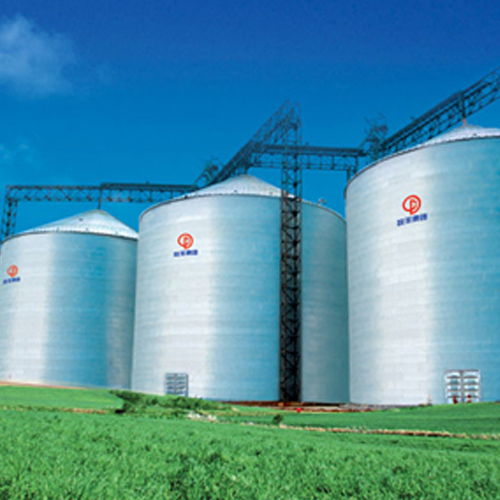
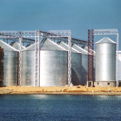
Bolt assembly type steel silo technology is the most advanced among the silo- building technologies in the modern world. Widely used in the American and European countries, bolt assembly type storage silo takes the largest market share in silo area. The modularized production avoids any human factor damages and increases accuracy, preventing damages to the zinc layer during installation. The sidewall and stiffeners are connected by detachable high strength bolts.


As an industrial company in large scale production of storage products, Muyang has modern workshop buildings and state-of-the-art production equipment, of which are complete production lines and technique for assembly type steel silo from USA and that from Switzerland, and silo fabricating equipment including the international first-rate YSTRONIC laser cutting machine as well.

The reason why the bolt silo is so great is that it has four distinct advantages, the first one is its large capacity, and silo roof angle is 35 degree, more storing space. Single grain silo capacity is up to 17000 tons, with comprehensive configurations to meet different customer’s requirements. It completes advanced processing equipment and technology introduced from USA to effectively ensure working accuracy and reduce damage to galvanized layer. External installable stiffeners contribute to less grain residues on silo walls. With standardized and modularized production, components and parts have a high standardization and good interchangeability, thus can be partially replaced or completely transferred.

Monday, October 21, 2013

Briefing of STHJ Series A-Type Paddle Molasses Mixer

The power is transferred from the motor to the rotor via sprocket. The molasses is blown into the mixer by steam. The paddles of the mixing machine are regularly staggered on the rotor along axial and circumferential directions in a certain angle to the rotor, so that a helical surface is formed between the paddles. When working, the rotor brings the feed to roll over and meantime push them to the discharging outlet.


STHJ Series A-Type Paddle Molasses Mixer consists of a rotor, a machine body, a bearing support, big and small belt pulleys, and guard shield. The mixing machinery body is composed of a trough, ring flanges, wall plates, a clearing gate, a feeding inlet and a discharging outlet etc. It is dismountable, and easy for the installation and replacement of the rotor, and a large clearing gate is convenient for cleaning of the rotor as well as replacement and adjustment of the paddles.

Molasses is blown in by steam via molasses adding pipes. The heating temperature of the molasses mixture is 32℃~38℃, and its viscosity should be less than 200 CP. The steam temperature on the paddle mixer is 130℃and the pressure is 0.3MPa. In order to prevent any accident in work of machine, the cleaning gate is equipped with an interlocking safety device, to ensure that the motor cannot be started when the cleaning gate is open.

Muyang also provide you with steel silo project, you can visit our site and leave messages there.

Friday, October 18, 2013

A Hanging Steel Silo

Steel silo is one of the main gram storage containers. Its disadvantages are: (1) steel strength used only about one third because of the buckling of it; (2) the pressure applied to the silo wall by the stored material will be doubled at time of unloading according to the silo code. So, more steel and fund are needed for construction.


The steel silo technology has been used for storing granular materials in China since the beginning of 80's, and it attracted many scholars to concentrate their attention in studying on this technology. It is well known that the steel silo belongs to thin-shell structure, and when the friction of the storage material to silo wall apexes axial compression, it is easy to buckle. The structure design of steel silo is controlled by buckling stead of by strength conditions and its buckling critical compressive stress is very smaller than its strength. On the other hand, axial tension is not to cause buckling, so that the structural design of storage silo is determined by its strength conditions instead of by its buckling conditions.

All types of steel silo used now can be styled the placing steel silo that is located at the supporting bed or the silo foundation. The function of the stored material makes it to be compressed in axial direction. The disadvantages of the placing steel silo are: (1) steel strength used only about one third because of the buckling of it; (2) the pressure applied to the silo wall by the storage material increases one times when unloading according to the silo code. With unloading of the storage material, the dynamic pressure on the silo wall exerted by the storage material changes very much which may result m the buckling of the steel silo. So, more steel and capitals are needed for construction to guarantee the safety of placing grain silo. In order to overcome the two disadvantages above mentioned of placing steel silo, the Hanging Steel Silo was designed.

Thursday, October 17, 2013

Muyang Steel Structure Plan

Muyang will create printed files of all inquiries and project data received under the name of the submitting company for evaluation or execution of the project. All information is considered confidential at all times and may not be shared or released for any reason without the consent of the client. In the case that Muyang will share or outsource production, the client must first approve the sharing of information. Furthermore, Muyang will not reveal specific information about other Muyang customers, their locations or projects unless this release of information has been previously approved by that client. All customers have a right to privacy and Muyang will comply with all NDA requests.


Every project inquiry is reviewed by Muyang engineers, production management, and senior management to ensure that your steel structure engineering and your company are a good match for cooperation. Confirmed projects will be sent to estimating. Muyang favors steel fabrication projects in the range of 100~1000kg/m, such as petrochemical plants, refineries, boiler structures, power plants, light and heavy industrial projects. We are also able to structural steel fabrication and secondary steel structures. Other aspects of the client are considered, such as client type, business type, location, scope of supply, schedule, delivery terms, payment terms, and ease of cooperation. It is always our opinion that the relationship comes before the project, so we do our best to make good choices during this stage.

Muyang Steel Structure Inspection and Test Plans include:
1. Purchase Order Number
2. Material / Equipment description
3. Legend
4. Applicable activities occurring during the fabrication / assembly
5. Control Procedures
6. Acceptance Criteria (Project Specification, Code reference, or both)
7. Verifying Document (Document that is generated after the activity is completed)
8. Vendors participation for each listed activity (Show which department or sub-vendor is responsible).
9. Purchaser / Client Participation (if applicable)
10. Establish and show holding points for quality controls. These activities depend on the vendor / supplier sledged)
11. NDT/NDE Requirements.

Wednesday, October 16, 2013

SJHS4A Paddle Mixer Installation Requirements

The paddle mixer is delivered generally as a complete set. Firstly check if there is any damage during transportation when unpacking; Installation field should be firm and roomy. When it is installed, leave an enough space for maintenance and replacement of fittings. Please refer to the scaled drawing of mixer installation provided when ordering; the proper maintenance platform and staircase should be provided if necessary, the staircase shall be equipped with guardrails.


This mixing machine should be fixed on a flat concrete base floor or a steel frame with enough strength by fixing onto the floor with foundation bolts. Or else, it will result in severe vibration or accident. Please refer to Table 4-1 for the tightening torque of the foundation bolts. Any accident caused by unsetting machine is out of Muyang's responsibility. A matched surge bin should be configured under the machine; a matched feeding device should be configured on the upper part of the machine. Adjust the rotating direction of the rotor to make it in accordance with that pointed by the arrow on the machine housing.


If a liquid application device is optioned, connect the liquid pipelines and the compressed air pipelines. Schematic diagram is for the connecting of liquid application system. If an air-sac blowing device is adopted, connecting to the electric power supply and air supply as per that shown in Fig.4-4 Schematic diagram for the connecting of air-sac blowing device. If a pneumatic cylinder of the mixing machinery is used to control the opening/closing of the door, connect it to the air source with a Φ12 plastics pipe according to Fig.4-5 Schematic diagram for connecting to air source. The upper end of air-return duct should be connected to the surge bin or somewhere above the scale so as to ensure stably feeding.

Tuesday, October 15, 2013

Brief on TPH260 Extruder

The whole TPH260 extruder can be divided into 4 parts: a feeder, a conditioner and a principal machine and a cutting cart. Corresponding safety marks are pasted on the required surface positions of these 4 parts, for detail see Fig.1.11~Fig.1.13. Each arrow directions in the figures point to the pasting positions and the numbers in the circle represent the contents in Table 1-2.


For example: In Fig 1-11, the position with mark "8" needs to paste the safety marks with No. "8" in the table 1-2, in other words, this position needs to paste the code "COMM65010005", and the safety mark named "clockwise direction".


In normal production of the extruder, the pressure in the extruding chamber is high; therefore the installation manner of the extruding machine has reached all the requirements of firm connection of the extruding chamber in theoretical calculation and practical application. However, the accidents have occurred such as "jetting out" of the extruding chamber or discharging device in the production due to improper installation, screw fatigue and so on. Therefore, it is required that no anyone stands at front of extruding chamber when the extruder is running.


If any accidents are caused due to not obeying the stipulations in the Operation Manual and the control system for Muyang machinery equipment is not used as per the conditions mentioned above, the Muyang will refuse to take any responsibility. If the Muyang is required to take responsibility, it will reserve the right to investigate and affix the responsibility of the operator.

Monday, October 14, 2013

Assembly of Rotor on MUZL350T Type Pellet Mill

The lubricating grease shall be filled in rotor of pellet mill and bearing of press roller by the semi-auto greaser at rear end of main shaft, and the oil way shall be kept straightway. A little lubricating grease shall overflow from the seaming of the sealing plate at end of press roller after being filled up in bearing of press roller; a little lubricating grease shall overflow from the clearance between the rotor and main shaft disc after being filled up in bearing of rotor.


You should pay attention to plug up the oil hole in the front end with the sunk screw first when installing the supporting shaft of the press roller. The hole is left when you do the oil pipeline machining, otherwise, the lubricating grease will overflow from this place.

The bearings and oil seal of the rotor are uneasy to be damaged. It is suggested to ask pellet mill experts of Muyang for guide when replacing bearings and oil seal.


Pay attention to abrasion of the cone face of driving rim of the ring die, and the safety operation of the whole pelleting machine will be affected due to mating precision of it and cone surface of ring die. In case the bolt of ring die is broken, generally, the driving rim should be replaced.

The semi-auto greaser must work with grease filter. A certain content of solid impurities is contained in the lubricating grease, and the impurities can be mostly removed by the filter. Regularly clean the filter screen to ensure the filtering effect.

Saturday, October 12, 2013

MNMP25 Iron Roller Rice Whitener

Muyang MNMP25 Type Vertical Iron Roller Rice Mill, which is used to produce completely cleaned rice, is adaptable for rice mills of producing 120~150 tons rice a day. If used together with Muyang MNML vertical type Sand Roller Feed Mill, it can produce rice with different grades as well as process and economic efficiency.


The wet iron roller rice mill can also be used as a rice polisher, which can make the white rice get a better polishing efficiency.

Any loss due to using out of application range or not related to design, like producing rice that not been fully cleaned, Muyang will be free of any responsibility.

Application related to design means when using this machine, the installation, operation, inspection as well as maintenance should strictly obey the rules and explanations in the operation manual.

MNMP25 Iron roller rice whitener is mainly composed of a feeding mechanism, a driving device, a whitening chamber, a discharging device, a blower, a bran sucking device and a dampening system etc.

The brown rice, after bran being removed in an emery roller rice whitener, is fed to the bottom of whitening chamber by the horizontal feeding screw, and then pushed down-to-up into the clearance between iron roller and screen segments by the screw propeller. The brown rice on the feed machinery is force to spiral up along the screw surface of the iron roller. It is the frictions generated between rice grain and iron roller, rice grain and screen that whiten the rice.

Feed Mill Industry Solutions

Muyang is the global leader in feed machinery manufacturing and engineering installation, feed machinery standardization and feed industry technological progress promotion. Muyang export products and solutions to more than 80 countries worldwide.

Muyang provides feed production industry with comprehensive solution of the widest range and the highest level of technology, from a single feed processing machinery and equipment to the entire feed production lines and the new animal feed mills multi-level comprehensive solutions. For example, for the new feed mill customers, Muyang overall solution include: overall design, plant, steel silo, transportation equipment, feed, machinery equipment, electronic control system, etc., providing users with high-quality, most intimate of "turnkey" engineering services.


Muyang not only provides customers with feed processing equipment and technology, but also provides customers with personalized service, maintenance and training opportunities to help feed factories to run in the most economical way and gain higher benefit and strong competitiveness.

Feed production solution design

(1)Determine the scale of feed mill
(2)Determine the feed process and recommend equipments
(3)Control mode selection
(4)Plant structure selection
(5)Planning the general drawing of plant site

Thursday, October 10, 2013

Explanation for Electric Part on Muyang Feeder

The electric elements on the automatic feeder shall be installed and operated according to their operating instructions, and their actions shall be accurate, reliable and flexible. The customer should provide an over-voltage protection device for power supply of this product.

In order to ensure the safety of working environment, please mount an emergency stop button at the place near the grinding machinery for convenience of workers' operation. The above schematic diagrams are only the running principle for a single machine of this product. The interlocking and linkage between the front and back technological equipment should be considered for design of control technological flow.

Prior to first startup, it is necessary tore move two cartridges clamping the magnetic gate at first, and the function of the cartridges is convenient for transport (when mounted in the air cylinder with magnetic gate).


After the feeder has been installed to its position, it is unnecessary to start the grinding machine for first startup and commissioning, so the starting and stopping switch shall be changed over to the starting position, to check firstly whether the feeding adjusting gate is being opened slowly or not.

The action procedure of the feeding adjusting gate is: quickly close it, and slowly open it within time delay for several seconds after the signal of the gate closed to its position has been detected. If the feeding gate on the hammer mill cannot be opened jet within about 40 s after startup, please shut down the power supply of the controller, and check the step motor for heat generation, and whether the switch of gate opened to its position is wired correctly or not, and the wiring in the controller of the step motor is loose or not. If the wiring is correct, but the step motor is heated up, so it indicates that the wiring of the step motor is wrong, and it is all right only by exchanging any two lines among U, V and W.

After the feeding adjusting gate works normally, please confirm whether the frequency of the frequency converter is normal or not, whether the feeding motor works normally or not.

After above several problems have been solved, the feeder can be put into normal operation.

Wednesday, October 9, 2013

How to Operate the Feed Mixer

The operator should well know the structure, performance and operating methods of the machine, and have received the training organized by Jiangsu Muyang. Each batch of material should be fed evenly in production and may not be sometimes more and sometimes less, so as to ensure the motor running under a rated load. After working, the paddle mixer must make an idle run for 1-2 min. prior to shutting down, so as to discharge all materials out of the machine.

If violent vibration occurs when the mixer is running, it should be stopped immediately to find out the cause and may only be restarted for work until the fault is eliminated. The temperature raise (refers to the risen temperature above ambient temperature) of the bearings for main shaft should not be higher than 35℃, and the maximum temperature should not be higher than 70℃ (ambient temperature should not be higher than 40℃). Carry out necessary cleaning and inspection when each shift of work is finished.


Materials cannot be fed until the rotor is running normally. Muyang refuses to responsible for all accidents that result from starting mixing machine with load Additives should be added in when half of the major materials has entered into the machine, and oil/fat should not be sprayed until all materials have entered the machine. Keep mixing for a certain period of time after spraying, and then discharge. When the machine is stopped and not to be used, oil/fat must be emptied out of the liquid pipe, so as to avoid pipe blockage due to oil solidification.

Metal or other large impurities should not be included in the material, or else rotor and paddles may be damaged. The speed reducer, cylinder and other accessories on the feed mixer should be used in accordance with the relevant stipulations in their operating instruction manuals. After a period of using, check the screws, nuts, and lubricating points for normal performance, and tight the other fasteners as well. Avoid overload running, so as to protect the main shaft from broken. Feeding amount of each mixing batch should strictly accord with that required in Table 2-2. Accident resulted for overload is not Muyang's responsibility. Before each restart, any residues in the mixer chamber must be emptied. Material cannot be fed until the rotor is running normally.