Sunday, December 29, 2013

Muyang Grain Silo

Whether your storage needs are for the farm, elevator or even large port facilities, Muyang has the expertise, diverse product line and proven experience that will provide you value well beyond the purchase. Muyang silo manufactures a full line of stiffened and un-stiffened farm bins (silos) as well as a complete line of stiffened steel silo.


We Muyang help installing Grain Storage Silo for our clients across the nation. Our prestigious installation of grain storage silos, with quality and strength of commercial grain storage tanks. The equipment used to manufacture commercial grain storage tanks is the newest and most advanced production equipment in the industry. These have an external bin stiffener that provide an excellent support and prevent the accumulation of grain and the resulting spoilage that can occur with internal stiffeners.

Muyang is one of the few suppliers in the world providing a single silo capacity of more than 10,000 tons. Muyang fabricated storage silo construction technology is the world's most advanced in steel silo construction. The type of silo is widely used in Europe and the United States with the highest share in the field of steel silo. Muyang produces silos in all molds to avoid human factors, so it features high quality and stability, and thanks to mold production, assembled on-site, there is no damage in zinc coating.

Friday, December 27, 2013

Tips to Choose the Best Silo

Silos are commonly used to store bulk materials. And how to choose right silos is usually a problem. Here I would introduce you some tips on grain storage silo.


Why do we need grain silos?

It is very important to keep the grains market-ready for sale. The grains should be kept dry. Storage bins should facilitate easy handling of the grains. Steel silo is meant to store grains safely so that you get a good return for the money invested. These silos come in different models. There are simple bins with a single auger to dry the grains and large complicated ones that are equipped with sophisticated mechanisms to handle and dry the grains.

Before investing in silos you must be aware of the choices available to you.

How to select the best grain silos?

Getting grain silos is a matter of huge investment. You must make sure that the investment you make gives you good return. The silos you built must last long and provide all the benefits you have been looking for. When it comes to choosing the material for storage silo you have a lot of options.

Generally the grain silos are built from metals, cement and bricks. Storing grains in metal silos is very common. You will find silos made from galvanized metal and smooth metal. But these are susceptible to rust and may not be safe for your grains. You cannot increase the capacity also when you have the need.

Tuesday, December 24, 2013

Assembly Type Steel Silo

Steel silos can be equipped with complete temperature control and ventilation system that guarantees the maintenance of the grain in good conditions, and it's not necessary to require the soil to be as firm in order to support the weight of the structure. Sometimes grain storage silo can be built on land that doesn't have the higher load-bearing capacity needed for concrete.

The assembly silo is made of high quality hot-galvanized steel plates which are rolled into corrugation and made into standard connecting holes. These plates are connected by high-strength screw bolts. The steel silo plates/thickness distribution is set according to equal strength theory which makes the silo plates bear average stress. The vertical friction is supported by the stiffeners. These stiffeners are evenly and vertically distributed in the silos. The connecting screw bolts are served with round galvanized steel washers and the connection holes are served with age-resistant and water-proof washers. The silo plates/interval is injected by water-proof daub belts that are for aviation special purpose. The grain silo is assisted with flat repairing doors, outside ladder, ladder guard rings.


Advantage of assembly type steel silo

***Large capacity
One single-silo capacity is up to 18,000 tons with comprehensive configurations to meet customers' different requirements.

***Good sealing performance
The silo is of a good sealing performance and can be used as a fumigating silo.

***Long service life
Best sheets match to silo body enables a normal service life up to 20-25 years.

***Detachable and movable
With standardized and modularized production, components and parts have a high standardization and good interchangeability, thus can be partially replaced or completely transferred.

Wednesday, December 18, 2013

Muyang Steel Silo

Muyang silo products could be sorted into two categories: Lipps Silo and Assembly Silo, of which we are extremely proud. We have already undertaken over 1000 storage projects around the world. In the steel silo market of China, both of those are ranked in the first place, as the reward of our ten years of hard work.

Our storage silo storage system has exported to more than 30 countries, such as: Vietnam, Thailand, Indonesia, Malaysia, Phlippines, Japan, Korea, India, Lebanon, Syria, Saudi Arabia, Iran, Kazakstan, Uzbekstan, Egypt, Tunisia, Libya, Sudan, South Africa, Brazil, Colombia, Australia, Turkey, Russia, etc. Muyang silos can be applied in the grain processing, oil & fat processing, flour processing, brewing, chemical and feed processing industry and ports and so on.


Principle of Lipps Silo Fabrication:
1st step: Send a galvanized coil sheet with width of 495mm into a cold-roll-forming machine by a coil opening machine to form into a geometric shape needed;
2nd step: Bend it by a bending machine;
3rd step: Seam bended sheets, so as to form a 30-40 mm wide continuous spiral-shaped high joint around the outside of the silo, which will strengthen the silo structure.

Assembly silo is a kind of the most advanced grain storage silo in the world, widely used in European and American countries and has the highest market share worldwide. Thanks to the automatic molded fabrication system, silo component parts are manufactured without any man-made impact.

Silo bins are assembled and erected on site, featuring no damage to the galvanized surface of sheet steel. The side boards and stiffeners are connected by means of high-strength bolts, and all of the silo parts are dismountable. Volume capacity from 1 ton to 18000 tons based on the bulk density of 0.75 g/cm3 .

Thursday, December 12, 2013

Explosion Resistant Silos

For storage of explosive solids, Muyang offers special steel silo with an explosion-resistant design. A distinction is made between silos that are pressure-tight (no deformation allowed) and pressure-shock-resistant (deformation allowed). The silos are designed for either the solid's maximum explosive pressure (up to 9 bar) or in case explosion pressure relief is used, for the reduced explosive pressure (generally 2 bar).


Muyang makes not only static calculations for pressure-shock-resistant storage silo, but also the calculations for the pressure relief surface. Its approved explosion flaps protect pressure-relieved silos. In the event of an explosion, the explosion flap will open and allow the silo to relief pressure. Unlike rupture disks, explosion flaps are self-closing and can be used again after an explosion. If needed, we equip explosion flaps with under pressure safety mechanisms and electric heating.

Muyang has decades of expertise in this field and guarantee its customers the highest quality and greatest safety.

Tuesday, December 10, 2013

Muyang Steel Silo Service

The success of companies which process high-quality polymers raises and falls by the quality of the raw material handling. Those seeking profitable solutions put their trust in Muyang and in the experience of an internationally successful industrial company. As a system supplier, Muyang supplies turn-key grain storage silo plants especially for the plastics processing industry. The services comprise with consultation and engineering, manufacture and commissioning.


The quality of our systems is the basis for your productivity. That's why Muyang offers not only silo plants, but also competent support, first-class service and an impressive service package, not to mention our top-quality products. From your point of view, this means lasting quality from a good source and hence an excellent return on your investment.

Muyang Steel Silo Features:

1. Over 40 years’ experience and rich expertise;
2. Wide storing capacity range, 1~18000 tons for single silo;
3. The biggest successful story: half million tons of silo project in Algeria;
4. Effective global sales network;
5. For storing wheat, large capacity;
6. From intake, cleaning system, dryer, silo.

Tuesday, December 3, 2013

Silo History

The design of silos for the storage of bulk granular materials and other bulk products has been the focus of research for more than 100 years with the early publications appearing in the literature spanning the period from the latter 1800's to the early 1900's.

While steel silo has been in existence for many centuries, the known published research into silo loads was performed over the period of some 30 years commencing in the early 1880's. A review of this early silo load research has been published by Roberts (1995, 1999). The most widely known work in the early period of storage silo research is that due to the German Engineer, H.A. Janssen (1895). This work is significant in that it recognized some fundamental aspects of internal and boundary friction which limit the magnitude of the loads on silo floors and walls.


Following the foundation work of Jenike, the study of bin wall loads gained new impetus (Jenike et al (1968-1973). With the flow modes clearly defined and the advantages of mass-flow being identified, the need for determining the wall loadings in mass-flow bins became a necessity.

Significant increases in wall loads may occur in grain storage silo due to increases in grain moisture content in combination with thermal expansion and contraction (Roberts (1998)). An example of such loadings has been identified as a contributing factor to the failure and collapse of the steel wheat storage silo in Australia.

Thursday, November 28, 2013

Geometry of the Experimental Silo

The principle components of the test station consist of a steel silo for storing the material to be tested and another, experimental silo containing the instrumentation necessary for measuring the actions of the stored material. The stored material is transferred between both silos using two screw conveyors powered by electric motors.

The geometry and dimensions of the test silo are shown in Figure 2. The silo is cylindrical, with a central hopper and a roof at the top. The silo body (a vertical cylinder), the hopper and the roof are independent and can be dismantled.


The storage silo walls were constructed from sheets of stainless steel 3 mm thick, whilst the cylinder, hopper and roof reinforcement rings were 50 mm wide and 10 mm thick. Given the dimensions and the type of material used for the walls, the silo can thus be considered a rigid, smooth-walled steel silo. According to the Euro code classification, it corresponds to a slender silo, since the cylinder height/diameter ratio is equal to 2 (hc/dc =2).

To measure normal wall pressures, a vertical generatrix was located on the cylinder wall, along which 7 readings were taken at the different heights indicated in, whilst hopper pressures were measured immediately below the grain storage silo hopper transition, at the prolongation of the generatrix mentioned above for measuring cylinder pressures. Double bending beam load cells were used to measure normal wall pressures. For this, 150 x 150 mm openings were made in the wall, into which panels of the same curvature were inserted, leaving a small gap around the edges.

Wednesday, November 27, 2013

Silo Technology --- Muyang

Muyang is the right partner for system, bin, energy and environmental technology. The company has more than 40 years of engineering experience and silo storage expertise, specializing in material storage technology research and development, design, installation and service.


Our grain storage silos are well known wherever bulk solids are stored, processed or transported. They come in capacity from 1 ton to 18000 tons. They have various designs, are made from different materials and are adapted to the demands of the solids being stored. For a sure and continuous discharge, there are a number of special discharge devices to choose from.

The assembly type steel silo's capacity is up to 18,000 tons with comprehensive configurations to meet customers' different requirements. Complete advanced processing equipment and technology are introduced from USA to effectively ensure working accuracy and reduce damage to galvanized layer. External installable stiffeners contribute to less grain residues on silo walls. With standardized and modularized production, components and parts have a high standardization and good interchangeability, thus can be partially replaced or completely transferred.

Monday, November 25, 2013

Muyang Silo Design

The design of bins and silos to store bulk solids involves bulk material, geometric, and structural considerations.

Bulk material considerations are important because the frictional and cohesive properties of bulk solids vary from one solid to another, and these properties affect material behavior considerably. In addition, a given bulk solid's flow properties can vary dramatically with changes in numerous parameters, including particle size, moisture, temperature, and consolidating pressure. This variability of properties makes testing at actual conditions more important for proper bin and storage silo design than at first appear.


When considering the geometric design of a steel silo, potential problems include arching across an outlet, rat holing through the material, and the flow pattern during discharge. A bulk material's propensity to arch or rat hole is primarily related to its cohesiveness, while its flow pattern during discharge depends upon internal friction as well as the friction that develops between the material and the silo's hopper walls. The goal of geometric design is to maximize the useable capacity of a silo while minimizing its capital cost, overall height, etc.

Friday, November 22, 2013

Basic Information on Muyang Silo

Steel silos are ubiquitous in manufacturing plants wherever dry granulated or powdered materials need to be stored. These silos vary in size and are usually supported by a steel frame on a reinforced concrete foundation. The steel silo loaded at the top by pumping the materials in using air pressure or using a conveyor. The silos discharge the materials to a truck or a freight car through a hop-per at the bottom.

Silo materials do not act like a fluid; dry materials have frictional or cohesive resistance and tend to form domes or "bridges" with the walls of the silo that prevent it from flowing freely downward. The lateral pressures on the grain storage silo shell from the dry materials are of a different character than the lateral pressures on a retaining wall from soil at the back of the wall. The vertical pressures on the bottom of the silo from the dry material are affected by the bridging action. In order to discharge the hoppers at the bottom, a vibratory system, called a bridge breaker that temporarily destroys the frictional resistance or cohesive bonds is required.


Features of Muyang steel silo

Large Capacity
One single-silo capacity is up to 18,000 tons with comprehensive configurations to meet customers' different requirements.

High Accuracy
Complete advanced processing equipment and technology are introduced from USA to effectively ensure working accuracy and reduce damage to galvanized layer.

Less Residues
External installable stiffeners contribute to less grain residues on storage silo walls.

Detachable and movable
With standardized and modularized production, components and parts have a high standardization and good interchangeability, thus can be partially replaced or completely transferred.

Tuesday, November 19, 2013

Muyang Insulation Silo Advantages

Muyang is the world's leading overall storage facilities and engineering solutions provider, in addition to providing steel silo, spiral silo and insulation silo, but also providing a comprehensive package of equipment and systems, including transportation equipment, drying equipment, as well as providing the overall design, construction, integration services.


Muyang insulation silo advantages are as followings:

Heat insulation
Silo inner grain temperature gradient changing slower than that of outside, not easy to condense

Safe grain storage
Store grain at low temperature, increase food storage stability, maintaining food quality and extend the safe storage time.

Low cost
For insulation storage silo, the insulation external wall is equipped with insulation layer (polyurethane foam, rubber foam, fiberglass, etc.), as compared with the concrete silo, low construction cost.

Currently Muyang marketing and service network cover around the world in more than 80 countries and regions with branches or offices. Muyang has a strong localized sales and service teams, providing global customers with localized pre-sales consulting, solution design, product customization, project implementation, equipment installation, maintenance, warranty and all other services.

Friday, November 15, 2013

Integrated Solutions and Turnkey Services

Muyang prefabricated corrugated steel silo using a full U.S. latest manufacturing technology and equipment, equipped with the most advanced computer system that provides users with 10 to 16,800 tons of different models of flat, conical bottom, fluidizing material and porous material discharging, its unique in China.


Muyang spiral steel silo use a full set of equipment and techniques from Europe, providing users with 50 to 7000 tons of different models of flat, conical bottom, fluidizing material and porous materials discharging, stable performance. Muyang is one of the few suppliers in the world providing a single silo capacity of more than 10,000 tons.

Muyang provides customers with turnkey projects ranging from technology process, civil engineering design, automation control systems to improved transportation, cleaning, magnetic separation, metering, drying, fumigation, refrigeration, ventilation, dust, temperature, humidity and other measuring equipment manufacturing, installation , commissioning and personnel training.

Single grain storage silo with capacity 10,000 tons (including the above) has been built hundreds, experienced. It takes the lead in the industry sales in consecutive years. Silos are widely used in food, oil, port, corn deep processing, flour, brewing, chemical, feed, building materials and environmental protection industry, well selling to nearly 100 countries and regions in the world like Egypt, Saudi Arabia, Iran, Thailand, India, Japan, United States, Malaysia with more than 5,000 projects totally.

Friday, November 8, 2013

Muyang Steel Silo Project --- Successful Stories Around the World

As an indstrial company in large scale production of storage products, Muyang Storage Co. has modern workshop bildings and international first-rate production equipment, of which are compelte production lines and technique for assembly type steel silo from USA and that for spiral type steel silos from Switzerland, and silo fabricating equipment including the international first-rate BYSTRONIC laser cutting machine etc. as well.


Muyang Storage Co. markets assembly type steel silos, spiral type steel silos and grain thermal insultion silos and  provides a large selection of matching equipment for the grain silo including buket elevators, en-masse conveyers, belt conveyers, pre-cleaners and dust collectors etc. Muyang also offers entire systematic engineering includes automatic control system, temperature and moisture easuring system, material conveying system, fumigating system, turning-over and cooling system, flat-bottom sweeping system, electric system, steel structure and civil work.

The fabricating technology for assembly type corrugated steel silo comes from the USA. Various spiral steel silos with different bottoms and discharges are available with storing capacity from 10T to 16000T.

The article is from: http://youtu.be/rwlBPCzejOE

Monday, October 28, 2013

Muyang Bolt Assembly Silo

Advanced production equipment and company's strict management system have forged an international first-class brand - Muyang.

Bolt assembly type steel silo technology is the most advanced among the silo- building technologies in the modern world. Widely used in the American and European countries, bolt assembly type storage silo takes the largest market share in silo area. The modularized production avoids any human factor damages and increases accuracy, preventing damages to the zinc layer during installation. The sidewall and stiffeners are connected by detachable high strength bolts.


As an industrial company in large scale production of storage products, Muyang has modern workshop buildings and state-of-the-art production equipment, of which are complete production lines and technique for assembly type steel silo from USA and that from Switzerland, and silo fabricating equipment including the international first-rate YSTRONIC laser cutting machine as well.

The reason why the bolt silo is so great is that it has four distinct advantages, the first one is its large capacity, and silo roof angle is 35 degree, more storing space. Single grain silo capacity is up to 17000 tons, with comprehensive configurations to meet different customer’s requirements. It completes advanced processing equipment and technology introduced from USA to effectively ensure working accuracy and reduce damage to galvanized layer. External installable stiffeners contribute to less grain residues on silo walls. With standardized and modularized production, components and parts have a high standardization and good interchangeability, thus can be partially replaced or completely transferred.

Monday, October 21, 2013

Briefing of STHJ Series A-Type Paddle Molasses Mixer

The power is transferred from the motor to the rotor via sprocket. The molasses is blown into the mixer by steam. The paddles of the mixing machine are regularly staggered on the rotor along axial and circumferential directions in a certain angle to the rotor, so that a helical surface is formed between the paddles. When working, the rotor brings the feed to roll over and meantime push them to the discharging outlet.


STHJ Series A-Type Paddle Molasses Mixer consists of a rotor, a machine body, a bearing support, big and small belt pulleys, and guard shield. The mixing machinery body is composed of a trough, ring flanges, wall plates, a clearing gate, a feeding inlet and a discharging outlet etc. It is dismountable, and easy for the installation and replacement of the rotor, and a large clearing gate is convenient for cleaning of the rotor as well as replacement and adjustment of the paddles.

Molasses is blown in by steam via molasses adding pipes. The heating temperature of the molasses mixture is 32℃~38℃, and its viscosity should be less than 200 CP. The steam temperature on the paddle mixer is 130℃and the pressure is 0.3MPa. In order to prevent any accident in work of machine, the cleaning gate is equipped with an interlocking safety device, to ensure that the motor cannot be started when the cleaning gate is open.

Muyang also provide you with steel silo project, you can visit our site and leave messages there.

Friday, October 18, 2013

A Hanging Steel Silo

Steel silo is one of the main gram storage containers. Its disadvantages are: (1) steel strength used only about one third because of the buckling of it; (2) the pressure applied to the silo wall by the stored material will be doubled at time of unloading according to the silo code. So, more steel and fund are needed for construction.


The steel silo technology has been used for storing granular materials in China since the beginning of 80's, and it attracted many scholars to concentrate their attention in studying on this technology. It is well known that the steel silo belongs to thin-shell structure, and when the friction of the storage material to silo wall apexes axial compression, it is easy to buckle. The structure design of steel silo is controlled by buckling stead of by strength conditions and its buckling critical compressive stress is very smaller than its strength. On the other hand, axial tension is not to cause buckling, so that the structural design of storage silo is determined by its strength conditions instead of by its buckling conditions.

All types of steel silo used now can be styled the placing steel silo that is located at the supporting bed or the silo foundation. The function of the stored material makes it to be compressed in axial direction. The disadvantages of the placing steel silo are: (1) steel strength used only about one third because of the buckling of it; (2) the pressure applied to the silo wall by the storage material increases one times when unloading according to the silo code. With unloading of the storage material, the dynamic pressure on the silo wall exerted by the storage material changes very much which may result m the buckling of the steel silo. So, more steel and capitals are needed for construction to guarantee the safety of placing grain silo. In order to overcome the two disadvantages above mentioned of placing steel silo, the Hanging Steel Silo was designed.

Thursday, October 17, 2013

Muyang Steel Structure Plan

Muyang will create printed files of all inquiries and project data received under the name of the submitting company for evaluation or execution of the project. All information is considered confidential at all times and may not be shared or released for any reason without the consent of the client. In the case that Muyang will share or outsource production, the client must first approve the sharing of information. Furthermore, Muyang will not reveal specific information about other Muyang customers, their locations or projects unless this release of information has been previously approved by that client. All customers have a right to privacy and Muyang will comply with all NDA requests.


Every project inquiry is reviewed by Muyang engineers, production management, and senior management to ensure that your steel structure engineering and your company are a good match for cooperation. Confirmed projects will be sent to estimating. Muyang favors steel fabrication projects in the range of 100~1000kg/m, such as petrochemical plants, refineries, boiler structures, power plants, light and heavy industrial projects. We are also able to structural steel fabrication and secondary steel structures. Other aspects of the client are considered, such as client type, business type, location, scope of supply, schedule, delivery terms, payment terms, and ease of cooperation. It is always our opinion that the relationship comes before the project, so we do our best to make good choices during this stage.

Muyang Steel Structure Inspection and Test Plans include:
1. Purchase Order Number
2. Material / Equipment description
3. Legend
4. Applicable activities occurring during the fabrication / assembly
5. Control Procedures
6. Acceptance Criteria (Project Specification, Code reference, or both)
7. Verifying Document (Document that is generated after the activity is completed)
8. Vendors participation for each listed activity (Show which department or sub-vendor is responsible).
9. Purchaser / Client Participation (if applicable)
10. Establish and show holding points for quality controls. These activities depend on the vendor / supplier sledged)
11. NDT/NDE Requirements.

Wednesday, October 16, 2013

SJHS4A Paddle Mixer Installation Requirements

The paddle mixer is delivered generally as a complete set. Firstly check if there is any damage during transportation when unpacking; Installation field should be firm and roomy. When it is installed, leave an enough space for maintenance and replacement of fittings. Please refer to the scaled drawing of mixer installation provided when ordering; the proper maintenance platform and staircase should be provided if necessary, the staircase shall be equipped with guardrails.


This mixing machine should be fixed on a flat concrete base floor or a steel frame with enough strength by fixing onto the floor with foundation bolts. Or else, it will result in severe vibration or accident. Please refer to Table 4-1 for the tightening torque of the foundation bolts. Any accident caused by unsetting machine is out of Muyang's responsibility. A matched surge bin should be configured under the machine; a matched feeding device should be configured on the upper part of the machine. Adjust the rotating direction of the rotor to make it in accordance with that pointed by the arrow on the machine housing.


If a liquid application device is optioned, connect the liquid pipelines and the compressed air pipelines. Schematic diagram is for the connecting of liquid application system. If an air-sac blowing device is adopted, connecting to the electric power supply and air supply as per that shown in Fig.4-4 Schematic diagram for the connecting of air-sac blowing device. If a pneumatic cylinder of the mixing machinery is used to control the opening/closing of the door, connect it to the air source with a Φ12 plastics pipe according to Fig.4-5 Schematic diagram for connecting to air source. The upper end of air-return duct should be connected to the surge bin or somewhere above the scale so as to ensure stably feeding.

Tuesday, October 15, 2013

Brief on TPH260 Extruder

The whole TPH260 extruder can be divided into 4 parts: a feeder, a conditioner and a principal machine and a cutting cart. Corresponding safety marks are pasted on the required surface positions of these 4 parts, for detail see Fig.1.11~Fig.1.13. Each arrow directions in the figures point to the pasting positions and the numbers in the circle represent the contents in Table 1-2.


For example: In Fig 1-11, the position with mark "8" needs to paste the safety marks with No. "8" in the table 1-2, in other words, this position needs to paste the code "COMM65010005", and the safety mark named "clockwise direction".


In normal production of the extruder, the pressure in the extruding chamber is high; therefore the installation manner of the extruding machine has reached all the requirements of firm connection of the extruding chamber in theoretical calculation and practical application. However, the accidents have occurred such as "jetting out" of the extruding chamber or discharging device in the production due to improper installation, screw fatigue and so on. Therefore, it is required that no anyone stands at front of extruding chamber when the extruder is running.


If any accidents are caused due to not obeying the stipulations in the Operation Manual and the control system for Muyang machinery equipment is not used as per the conditions mentioned above, the Muyang will refuse to take any responsibility. If the Muyang is required to take responsibility, it will reserve the right to investigate and affix the responsibility of the operator.

Monday, October 14, 2013

Assembly of Rotor on MUZL350T Type Pellet Mill

The lubricating grease shall be filled in rotor of pellet mill and bearing of press roller by the semi-auto greaser at rear end of main shaft, and the oil way shall be kept straightway. A little lubricating grease shall overflow from the seaming of the sealing plate at end of press roller after being filled up in bearing of press roller; a little lubricating grease shall overflow from the clearance between the rotor and main shaft disc after being filled up in bearing of rotor.


You should pay attention to plug up the oil hole in the front end with the sunk screw first when installing the supporting shaft of the press roller. The hole is left when you do the oil pipeline machining, otherwise, the lubricating grease will overflow from this place.

The bearings and oil seal of the rotor are uneasy to be damaged. It is suggested to ask pellet mill experts of Muyang for guide when replacing bearings and oil seal.


Pay attention to abrasion of the cone face of driving rim of the ring die, and the safety operation of the whole pelleting machine will be affected due to mating precision of it and cone surface of ring die. In case the bolt of ring die is broken, generally, the driving rim should be replaced.

The semi-auto greaser must work with grease filter. A certain content of solid impurities is contained in the lubricating grease, and the impurities can be mostly removed by the filter. Regularly clean the filter screen to ensure the filtering effect.

Saturday, October 12, 2013

MNMP25 Iron Roller Rice Whitener

Muyang MNMP25 Type Vertical Iron Roller Rice Mill, which is used to produce completely cleaned rice, is adaptable for rice mills of producing 120~150 tons rice a day. If used together with Muyang MNML vertical type Sand Roller Feed Mill, it can produce rice with different grades as well as process and economic efficiency.


The wet iron roller rice mill can also be used as a rice polisher, which can make the white rice get a better polishing efficiency.

Any loss due to using out of application range or not related to design, like producing rice that not been fully cleaned, Muyang will be free of any responsibility.

Application related to design means when using this machine, the installation, operation, inspection as well as maintenance should strictly obey the rules and explanations in the operation manual.

MNMP25 Iron roller rice whitener is mainly composed of a feeding mechanism, a driving device, a whitening chamber, a discharging device, a blower, a bran sucking device and a dampening system etc.

The brown rice, after bran being removed in an emery roller rice whitener, is fed to the bottom of whitening chamber by the horizontal feeding screw, and then pushed down-to-up into the clearance between iron roller and screen segments by the screw propeller. The brown rice on the feed machinery is force to spiral up along the screw surface of the iron roller. It is the frictions generated between rice grain and iron roller, rice grain and screen that whiten the rice.

Feed Mill Industry Solutions

Muyang is the global leader in feed machinery manufacturing and engineering installation, feed machinery standardization and feed industry technological progress promotion. Muyang export products and solutions to more than 80 countries worldwide.

Muyang provides feed production industry with comprehensive solution of the widest range and the highest level of technology, from a single feed processing machinery and equipment to the entire feed production lines and the new animal feed mills multi-level comprehensive solutions. For example, for the new feed mill customers, Muyang overall solution include: overall design, plant, steel silo, transportation equipment, feed, machinery equipment, electronic control system, etc., providing users with high-quality, most intimate of "turnkey" engineering services.


Muyang not only provides customers with feed processing equipment and technology, but also provides customers with personalized service, maintenance and training opportunities to help feed factories to run in the most economical way and gain higher benefit and strong competitiveness.

Feed production solution design

(1)Determine the scale of feed mill
(2)Determine the feed process and recommend equipments
(3)Control mode selection
(4)Plant structure selection
(5)Planning the general drawing of plant site

Thursday, October 10, 2013

Explanation for Electric Part on Muyang Feeder

The electric elements on the automatic feeder shall be installed and operated according to their operating instructions, and their actions shall be accurate, reliable and flexible. The customer should provide an over-voltage protection device for power supply of this product.

In order to ensure the safety of working environment, please mount an emergency stop button at the place near the grinding machinery for convenience of workers' operation. The above schematic diagrams are only the running principle for a single machine of this product. The interlocking and linkage between the front and back technological equipment should be considered for design of control technological flow.

Prior to first startup, it is necessary tore move two cartridges clamping the magnetic gate at first, and the function of the cartridges is convenient for transport (when mounted in the air cylinder with magnetic gate).


After the feeder has been installed to its position, it is unnecessary to start the grinding machine for first startup and commissioning, so the starting and stopping switch shall be changed over to the starting position, to check firstly whether the feeding adjusting gate is being opened slowly or not.

The action procedure of the feeding adjusting gate is: quickly close it, and slowly open it within time delay for several seconds after the signal of the gate closed to its position has been detected. If the feeding gate on the hammer mill cannot be opened jet within about 40 s after startup, please shut down the power supply of the controller, and check the step motor for heat generation, and whether the switch of gate opened to its position is wired correctly or not, and the wiring in the controller of the step motor is loose or not. If the wiring is correct, but the step motor is heated up, so it indicates that the wiring of the step motor is wrong, and it is all right only by exchanging any two lines among U, V and W.

After the feeding adjusting gate works normally, please confirm whether the frequency of the frequency converter is normal or not, whether the feeding motor works normally or not.

After above several problems have been solved, the feeder can be put into normal operation.

Wednesday, October 9, 2013

How to Operate the Feed Mixer

The operator should well know the structure, performance and operating methods of the machine, and have received the training organized by Jiangsu Muyang. Each batch of material should be fed evenly in production and may not be sometimes more and sometimes less, so as to ensure the motor running under a rated load. After working, the paddle mixer must make an idle run for 1-2 min. prior to shutting down, so as to discharge all materials out of the machine.

If violent vibration occurs when the mixer is running, it should be stopped immediately to find out the cause and may only be restarted for work until the fault is eliminated. The temperature raise (refers to the risen temperature above ambient temperature) of the bearings for main shaft should not be higher than 35℃, and the maximum temperature should not be higher than 70℃ (ambient temperature should not be higher than 40℃). Carry out necessary cleaning and inspection when each shift of work is finished.


Materials cannot be fed until the rotor is running normally. Muyang refuses to responsible for all accidents that result from starting mixing machine with load Additives should be added in when half of the major materials has entered into the machine, and oil/fat should not be sprayed until all materials have entered the machine. Keep mixing for a certain period of time after spraying, and then discharge. When the machine is stopped and not to be used, oil/fat must be emptied out of the liquid pipe, so as to avoid pipe blockage due to oil solidification.

Metal or other large impurities should not be included in the material, or else rotor and paddles may be damaged. The speed reducer, cylinder and other accessories on the feed mixer should be used in accordance with the relevant stipulations in their operating instruction manuals. After a period of using, check the screws, nuts, and lubricating points for normal performance, and tight the other fasteners as well. Avoid overload running, so as to protect the main shaft from broken. Feeding amount of each mixing batch should strictly accord with that required in Table 2-2. Accident resulted for overload is not Muyang's responsibility. Before each restart, any residues in the mixer chamber must be emptied. Material cannot be fed until the rotor is running normally.

Wednesday, September 25, 2013

Operation of Soybean and Powdery Extrusion

Even Muyang's extruder can solve all your matters, but you should still know what should be done when you face different materials in extruding. Generally, you may choose two materials with both soybean and powdery feed. Following is two ways for extruding:

Operation of soybean extrusion

Main process: preheat → install discharging chamber → adjust discharging screw plug → start the main motor → install the protective hood (without water add device → start feed motor, set the feeding frequency at about 10~12HZ, raise the feed rate gradually after the main motor current is decreased to ensure the stable and continuous producing.

Explanation:
——Screw down the screw plug by use of special wrench, loosen back for 3~4 circles;
——Screw down the screw upper the discharging chamber, fix the discharging screw plug;
——Start the main motor and feeding device of the extruding machine, increase feeding gradually, then install the protective hood;
——Replace the screw plug with different aperture(Φ 8, Φ 10) and adjust the position of discharging screw plug so as to get the different soybean flour output;
——The operation above mentioned should be done quickly to ensure the preheat effect.


Main controls parameters under normal running (for reference)
Current of main motor 95~100A
Temperature at the discharging part 125~135℃

Operation of powdery feed extrusion

Main process: preheat → install cutting device → start main motor → start feeding device → start cutting device → adjust feeding device to normal operation state → install protective hood

Explanation:
——Fix the machine frame to avoid forward and backward movement after install the cutting device;
——Install different die and adjust cutting speed to get the material in different length and size;
——The add water volume can be set before Preheat.

Main controls parameters under normal running (for reference)
Current of main motor 90~100A
Temperature at the discharging part 110~125℃
Water pressure (select) 0.20~0.35Mpa

It is necessary to know how to operate the extruding machines, and it is also important to manage how to operate for shutdown. Close the water inlet valve first and stop feeding, and then stop the cutting device and principal machine. Remove the discharging device immediately after shutdown, clean the discharging device, after that restart the main motor, add a certain amount of soybean flour to clean away the rest material in the extruding chamber and lubricate it, so as to facilitate the next startup.

Tuesday, September 24, 2013

Spare Parts on SJHS2A Double-circle Paddle Mixer

Our works is responsible for repairing or replacing parts (exclusive wearing parts) which are faulted due to manufacturing quality within one year from the date of leaving the factory under normal use and safekeeping by the customer, excluding the operations not in accordance with the operating instructions and human factor.

Our works continues to undertake maintenance and repair on the mixing machines after one year from the date of leaving the factory, to ensure normal use of the customer, but the expenses shall be borne by the customer.


Some parts and components in this mixing machinery are worn off gradually when in use. If these parts are still used after worn to a certain degree, the property of equipment will be affected and dangerous accidents will occur probably. Therefore, these parts and components shall be replaced timely after used for a certain period. The spare parts in this Operation Manual is also called wearing parts.

Whether the spare parts can be ordered timely and accurately will influence your production. So in order to purchase right spare parts, when place an order, please mention the corresponding serial number, code, description of the spare part and the quantity needed in the order list (see Section 7.3 Ordering list of spare parts). And provide us the order list via mailing or e-mail; if possible, please attach a sketch of the spare parts you require.

Sunday, September 22, 2013

Main Structure on MUZL 610TW Type Pellet Mill

MUZL 610TW Type Pellet Mill mainly consists of a feeder, a conditioner and a principal machine of pellet mill (mainly including two main motors, an assembly of rotor, a ring die, press rollers, two assembly of cutting knives, a lifting device for the ring die and a lubrication system) (Fig 2.1).

1. Feeder
2. Conditioner
3. Lifting beam
4. Magnet
5. Assembly of cutting knife
6. Main motor
7. Shear pin
8. Lubricating system
9. Ring die
10. Roller
11. Scraper


The working procedure is shown as follows:

The mixed mash enters the feeding auger from the pelletizing chamber in a proper feeding amount through adjusting the rotating speed of the frequency control motor, and then enters the conditioner. The material will be sufficiently mixed with steam in the conditioner by stirring paddles of the conditioner, and molasses or oil can be added through the feeding inlet for molasses if necessary. The temperature of conditioned compound mash is normally controlled within 65~95℃ and the humidity 14~18% based on different formulas, and finally the material enters the pelletizing chamber and is pelletized to pellets by the press rollers and the ring die.

Feeder

The feeder on the pelleting machine is composed of a frequency control motor, a speed reducer, a sprocket driving device, an auger shaft and auger housing.

The frequency variable speed control motor is composed of a frequency conversion motor and a speed reducer. Working with the frequency converter, output rotating speed of the motor can be changed. (See Operation Manual of Speed Control Motor and Operation Manual of Frequency Converter for details).

A cycloid pin gear speed reducer with a speed reducing ratio of 1:17 allows the feeding auger to regulate speed in a range of 0~100 r/min.

Conditioner

A common conditioner is composed of a motor, a main shaft, paddles, a case, a steam inlet and the molasses inlet.

The conditioner case is made of stainless steel and the paddles are made of high alloy wear resistant material or stainless steel.

The conditioner serves the function of introducing steam with a certain pressure, and at the same time adding a proper amount of oil and molasses through the feeding inlet for molasses as required for conditioning compound feed to a certain temperature and humidity, so as to improve the feed value and pelletizing performance of the feedstuffs themselves. Refer to the next section for the steam system of the conditioner.


Steam system

Fig 2.2 shows the schematic diagram of pipeline for conditioner. Steam is generated by the boiler. The pressure of steam provided by the boiler shall be not less than 0.7 MPa, and the steam supply amount is calculated on the basis of 50 kg per ton pellet plus loss. Generally, the steam pressure in the main pipe shall be not less than 0.7 MPa, and the pressure of steam entering the conditioner after being depressurized by relief valve is within 0.1~0.4 MPa.

Wednesday, September 18, 2013

Electric Connection While Operating the Pellet Mill

Connect the principal machine, control system and control cabinet with power supply according to local rules and regulations for electric connection.

Lay the power cables and install the circuit protection breakers according to power voltage and motor power as well as the stipulations of the supplier. Correctly connect and check all grounding wires.

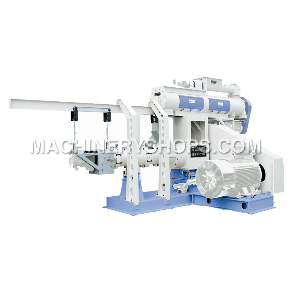
Lay the power cables for the control and high voltage cabinets on the installation site. Touch screen or The local control box shall be installed at a distance of 0.5m ~ 3m on the right side (preferred) of the pellet mill or installed at a distance of 1.0m ~ 3m on the left side of the machine.


The motors shall be interlocked with each other when laying power cables, and switched on according to following sequence:
①Motor for Hydraulic system ( if required)
②Main motor for the pellet mill
③Motor for the conditioner
④Motor for the feeder

There shall be an unlocking device between the main motor and conditioner, so it needs not startup the main motor when star ting the conditioner individually. Connect the motors correctly while adjusting its rotating direction.

The working principle and operation flow of the control box show as follows:

Commissioning process:

Make sure all the preparation works of pelleting machines are ready, the electric connection have been completed.
And then close each circuit breaker;
Release the lock emergency stop button E-STOP;
Switch the unlocking switch SA1 to the unlocking position, start up and shut down each electric motor to check whether it normal works.

Normal starting process:

Switch the unlocking switch SA1 to the interlock position, trigger starting button SB3+, start up the main motor of pellet mill and wait for one minute, trigger starting button SB2+ after its steady operation, start up the conditioner and wait for 30 seconds, trigger starting button SB+, start up the motor of feeder;


Explanation of working process:

The feeding frequency can be changed by adjusting the knob RP2 into a change of feeding amount, frequency meter PF21 can real-time display the operating frequency of feeding motor.

Temperature instrument U2 can real-time display the Material Temperature at the discharge hole of conditioner, the Material Temperature at the discharge hole can be adjusted by charging the steam additive amount in conditioner;

Shut down the feeding motor when the working current of main motor of the pelleting machine is more than rating or it increase rapid within the rated current interval, switch to the selecting switch SA2, electrified the by-pass solenoid valve, thereby opening the by-pass gate, the feeds will be discharged from by-pass gate and the motor load of pellet mill will be reduced. After the motor load returns to 50% of the rating, restart the feeder, gradually increase the feeding amount.

Stopping process:

Shut down the feeder first, wait for ca.10 minutes and then shut down the conditioner, shut down the main motor and cut off the general power after the working current of main motor reducing into the range of no load current. The handling of leak, electric shock, stoppage or severely overload: Press the emergency stop button immediately, to avoid the accident of casualties and motor damage.

Tuesday, September 17, 2013

Operating Instruction of Pipelines for MY-120/14D Extruder

The piping systems for Muyang-MY120×2/14DTwin-Screw Extruder are divided into two parts, namely water piping and steam piping. The important parts and components in the whole systems are adopted imported products, which are adjusted and controlled by PLC systems. We hope that the customers can read the Operation Manual carefully and then correctly operate and use the equipment, so as to ensure the safety in production; otherwise, the customers should be responsible for any consequence resulted.


Operating instruction:

1. It is required to provide clean tap water for the water box;
2. It is required to provide dry and filtered compressed air with a stable pressure of 0.5 MP for the adjusting valve;
3. First turn on the bypass when trying out the water piping for extruding chamber and conditioner, namely turn on all valves in the water piping (close the ball valves at both sides of the flow meter and adjusting valve);
4. After the water pump is started, adjust t he pressure of pressure reducing valve, so as to make the reading on the manometer is stabilized at a certain value between 0.4~0.6 MP after the pressure is reduced;
5. Close the bypass on the feed extruder, turn on the ball valves at both sides of the flow meter and adjusting valve, so as to allow water pass through the flow meter and adjusting valve, and then carry out adjustment on the operating screen;
6. In normal case, the water in conditioner is sprayed out stably; otherwise, it is necessary to check whether t he pipeline is blocked or not;
7. According to water quality, the filter shall be opened once a month or half a month, to remove impurities from the filter screen;
8. In case of normal work, the brass stop valve is normally opened, while the stop valve at the side of main part of extruder shall be opened each time when the machine is shut down.

Monday, September 16, 2013

Structural Features on Chaoyue SWFP Series Fine-grinding Hammer Mill

The materials to be ground are fed in from the feeding inlet on top of the grinding machine by a matching feeding mechanism, and enter the grinding chamber from the left or right side via a guide plate. The materials are ground gradually under the impact of hammers rotating at a high speed and the rubbing action against the screen, then pass through the screen apertures under the effects of centrifugal force and airflow, finally were discharged from the outlet at base frame.

Of a welded steel structure, the hammer mill consists of a base, an upper housing, a rotor, an access door, a screen hold-down mechanism, a feed guiding device and etc. The inlet and outlet locate at top and bottom centers respectively. The driving motor and the rotor are mounted on same base, and direct driving is realized by means of an elastic straight pin type coupling or an elastic pin type coupling (for SWFP66×125).


Structure of the key component parts

Rotor
The rotor consists of a main shaft, hammer carrier discs, shaft pins, hammers, bearings and etc, and it is main moving part of grinding machinery. Only those hammers with a thickness of 4 mm can be used for hammer replacement, and they must be fixed in accordance with the hammer arrangement plan, additionally, the difference between the total mass of the hammers of the two symmetrical groups should not exceed 2g.


Screen
Fitted inside the screen hold-down mechanism, the screen is easy to be replaced.
Feeding guide mechanism
It guides the feed flow to enter the grinding chamber from the left or right side of the machine. Diversion of the material guiding plate is controlled by the cylinder, and motor rotation direction will be automatically changed to suit the feeding direction.
Safety guard
To avoid any accident in operation, the access door is equipped with an interlocker so as to ensure that when the access door is opened the motor can never be started. (Fig 1)

Thursday, September 12, 2013

How to Operate the SWFL 110B/C Pulverizer

Firstly start up the motors of the air lock of each discharger on the grinding machine, and then the air compressor of the pulsed dust collector, and then start up the motor for grading impeller, high pressure fan and main motor in turn. Only when the main motor runs stably, the motor of the screw feeder can be started up. Prior to starting up the fan, firstly close the air gate of the exhaust system, and then start the fan, finally open the air gate till the fan goes into normal run.

Firstly adjust the motor of the screw feeder to the minimum rotating speed, and then slowly increase the rotating speed of the motor according to the current of the motor for grinding; adjust the motor to a proper rotating speed, keep the current of the motor for grinding within the rated current range, and keep it run with an optimal load.

Control the particle size by changing the rotating speed of the grading impeller and adjusting the air volume.

When the grading impeller of the grinding machinery runs at a higher rotating speed, the graded particle size (i.e. particle size of finished product) is smaller, contrarily the particle size is bigger. The particle size of finished product can also be controlled by adjusting the volume of air flowing across the fan and changing the grading positions; when the volume of air flowing across the fan is higher, the particle size of finished product is bigger, when the volume of air is lower, and the particle size is smaller.

The feeding amount also varies with the change of particle size of the finished product. When increasing the rotating speed of the grading impeller or reducing the air volume, the particle size of finished product will become smaller, so the ground materials retention in the grinding machines as well as the current values of the motor for grinding and the motor for high pressure fan in the pneumatic conveying system will increase, vice versa. Therefore, the feeding amount will decrease or increase correspondingly as well. During the production, it is necessary to adjust the particle size of finished product and the feeding amount under the condition of that the motor for grinding and the motor for the high-pressure fan cannot run with exceeded current.

The stop sequence of the equipment is opposite to the startup sequence. That is, firstly close the gate under the grinding bin, and then shut down the motor for feeding, the fan and the motor for grading impeller, finally shut down the motor for grinding and the motor for the air lock.

Wednesday, September 11, 2013

Muyang Brand MY 90×2S Twin-Screw Extruder

MY90×2S Type Twin-Screw Extruder is mainly applicable for production of floating aqua feed, sinking aqua feed, expanded rich noodle and expanded foods.

The extrusion provides for production of many products with great superiority in comparison with other technologies. Because it integrates functions of different equipments in a single process when extruding in most cases, the procedures of mixing, extruding, cutting, cooking, forming and drying process in a certain degree can be carried out at the same time.

In comparison with single screw one, twin screw extruder has a great superiority in a series of performance indexes such as curing degree of product, pellet uniformity, pellet surface roughness, ingredient scopes applicable for processing and so on.

Special assembly screw structure is applied, so that various products can be produced if only simply changing screw arrangement or changing manufacturing and processing parameters. Other technologies are difficult to or can hardly produce products and products in certain shapes which were produced by this extruding operation.

This extruding machine operation is extremely effective for high-temperature and short-period processing, it is provided with a better nutrition improvement while effectively reducing different anti-nutritional factor s in products and sterilizing. The cooking process of this extruding operation can cure material in a great degree, sufficiently use steam and reduce power consumption, and thus process cost can be saved. Flow and flow ratio of all materials can accurately controlled by an auto control system, and different processing parameters can be recorded, so as to provide a basis for future production or adjustment of processing parameters.

This extruding machinery operation can effectively avoid industrial wastewater; this is an outstanding advantage for feed manufacturers bearing the increasing pressure for reducing influences of production activities on surrounding environment.

Working Principle on Pellet Mill

This machine mainly consists of a feeder, a conditioner and a principal machine of pelleting machine (mainly including a main motor, an Assembly of rotor, a ring die, press rollers, an assembly of cutting knives and a lubrication system).


Working procedure:

The mash with water content less than 18% as required enters the feeding auger from the pelletizing chamber in a proper feeding amount through adjusting the rotating speed of the frequency control motor, and then enters the conditioner. The material will be sufficiently mixed with steam in the conditioner by stirring paddles of the conditioner, and molasses or oil can be added through the feeding inlet for molasses if necessary. The temperature of compound mash is normally controlled within 65~95℃ and the humidity 14~17% based on different formulas, and finally the material enters the pelletizing chamber and is pelletized to pellets by the press rollers and the ring die.

The principal machine on the pellet mill is composed of main motor, magnetic plate, Assembly of rotor, pelletizing chamber (including assembly of press roller, assembly of front plat and ring die), machine body, door and so on, Fig 1.5 shows the section of MUZL350TA type pellet mill. To ensure safety, this machine shall be used in the areas with an altitude lower than 1000m, a temperature from -5℃ to 40 ℃ and an air relative humidity from 30% to 95%. If the area does not conform to above conditions, please indicate specially when ordering. This machine is specially used for feed processing, generally for processing powdery, foldable and easily pelleted materials. Do not use it for processing of food.

Tuesday, September 10, 2013

Structural Features and Working Principle on SWFL82B

As the best grinding machine manufacturer, Muyang has made its efforts to make its all machines with high qualities. SWFL82B Vertical Pulverizer, as a new type of equipment for large-, medium- and small-sized feed mills, is with full equipments which make it more efficient.

SWFL82B ultra-fine pulverizer mainly consists of a stander, a grinding system, a grading system, a feeding system, a pneumatic opening mechanism as well as a driving part for grinding of the principal grinding machine and a motor driving part for grading. The grinding system is composed of a main shaft, a grinding disc, a geared ring and a grinding chamber; the grading system is composed of a grading impeller shaft, a grading impeller, a convex cover and a discharge chamber. The main motor runs in vertical driving way; the frequency conversion motors with frequency converters are used for both grading and feeding, so as to realize speed regulation and remote control.


After preliminary cleaning and magnetic separation, the raw materials (<1 mm) enter the grinding chamber from the screw feeder for grinding. Under a high-speed rotation of the grinding disc and an action of centrifugal force, the materials are ground by impacting of the hammer knives on the grinding disc, and fly to the surrounding geared ring in a very high speed. Since the clearance between the hammer mills knives and geared ring is very small, the airflow between the hammer knives and geared ring varies instantaneously with the change of tooth forms. The materials in the clearance are further ground under the repeated action of alternating stress. The ground materials are taken by airflow to the space between the inner wall and the dividing flow cover from the grinding disc, and then enter the grading chamber; the materials are graded under the collective action of rotary grading impeller, wind power and centrifugal force, and the separated course materials return to the grinding chamber for regrind from the inner chamber of the dividing flow cover, while fine materials (finished products) are sucked into the grading impeller and enter the discharge chamber, and then enter the collection system from the discharge outlet.

Friday, September 6, 2013

Extruding Assembly on Twin Screw Extruder

The extruding assembly is a key part of the extruder and mainly composed of an expanding chamber and an extruding screw. Classified based on its function, the whole extruding assembly is mainly composed of a feeding section, a kneading section and a final ripening section. But there is no strict limit between all the sections and they are designated according to their main functions.

A sectional integrated structure is applied for the feed extruder chamber and the cross section of inner hole likes the shape of "8". Each sect ion of chamber body has an individual external jacket chamber, which can be used for heating or cooling of the chamber body. In addition, there is a temperature sensor and the chamber is equipped with a pressure transmitter for detecting the working pressure in the expanding chamber. The first section chamber, the middle section chamber and the discharge chamber are equipped with water-steam valve. If it is necessary to add water during production, the water can be injected from the water-steam valve in the first section chamber; if it is necessary to add steam during production, the steam can be injected from the water-steam valves in the middle section chamber.


The extruding machine screw is a sectional assembly with hollow screw and positioned to the main shaft with integral key, and screw combination can be done based on material varieties and formula because the structural screw is universal and exchangeable.

Wednesday, September 4, 2013

Muyang won the "2012 China top ten grain and oil machinery manufacturing enterprises."

On August 29, 2013, Chinese vocational education and food industry dialogue on "top 100 Chinese Entrepreneurs" were premiere held in Beijing, China.

The theme of the dialogue was to promote integration of production and education, deepen the school-enterprise cooperation, cultivate the skilled talents, serving the modern food industries. The activity was host by Ming Xu who is the Deputy Secretary at State Grain Administration. Kaidao Ge, Ministry of Education, read out the whole party members, and Xin Lu, as an undersecretary, specifically made a written statement.

Xin Lu put forward four points on the future of food reform and development: Firstly, it was necessary to establish an integrated and coordinated working mechanism; secondly, enhancing the quality of the training industry was also important in current situation; thirdly, we should give full play to industry organizations; fourthly, the organization should reinforce policy funding. Lu emphasized that it would be a successful experience relying on the vocational education which was also an international practice. He also came up with the idea to accelerate the development of modern food vocational education, strengthen food professional education teaching reform, and improve the quality on personnel training. The education sector and the food sector should build together a number of food vocational colleges which can cultivate more skilled talents.

Ming Xu, in his speech, pointed that food industry was not only a traditional industry, but also a developing one with high knowledge and high technology. To ensure national food security, Government required a large number of skilled professionals, and strengthening school-enterprise cooperation was an important way to train highly qualified technical skilled personnel.

Subsequently, the Sichuan Grain University, COFCO Limited, Jiangxi Vocational and Technical College of Trade and Industry, LiHaiJiaLi Group, Guangxi Business Technology Institute, Muyang Group, Wudeli Flour Corporation and other seven schools and businesses made the final speeches.

Also, the event also released its 2012 annual key findings on the special grain and oil companies, issuing certificates as to top 50 enterprises, as China Quality Inspection Association member, Muyang Group won the "2012 China top ten grain and oil machinery manufacturing enterprises."

Finally, it held a the premiere on "top 100 Chinese Entrepreneurs (food stamps)" , the chairman, Minyue Li of Muyang Group was selected the successful one.

The article is from Muyang Group news : http://www.machineryshops.com/news/view/202.html?type=news

Thursday, August 29, 2013

Muyang SJHS0.5B Double-circle Paddle Mixer

The SJHS0.5B Double-circle Paddle Mixer is widely used for mixing powdery and special granular materials in feed industry.


Main features and functions

The SJHS0.5B Double-circle mixing machine is a kind of horizontal batch mixer;
With patented rotor structure, it is characterized by Short mixing period and high mixing homogeneity: The mixing homogeneity of material within 60~90S amounts to CV≤5%, reduce the mixing period and improve the production efficiency; (Methyl Violet Stain (GB/T5918) method is used to test the CV value of mixed product).
Large variable range of filling factor: The Filling factor is between 0.4~1, applicable for mixing the materials with different specific gravity and granularity in various industries.
The shaft seal adopts the unique sealing technology, reliable seal, no leakage and long service life.
The discharge gates adopt full-length opening structure, which contributes to fast discharge and little residues.
The seal of discharge gates on the mixing machinery adopts the unique sealing technology, reliable seal and no leakage.
Available of rise and fall type liquid application system, which is convenient and rapid for cleaning and replacing spraying nozzles and can spray liquid evenly.
With air-return mechanism, the pressure difference between inner and outer of the mixer can be well balanced when feeding or discharging.

Tuesday, August 27, 2013

Transportation and Installation

1. Hoisting
It can be seen from the following picture how the mixing machine is hoisted by a traveling crane. The rope must be capable of bearing the weight of equipment, and too short a rope is not usable. The lifting ears for hoisting are provided.


2. Transportation
When the mixing machinery is to be delivered out of the manufacturer’s plant, it can be decided according to the practical conditions whether a packing case should be used or not. If the packing case is not used, rainproof facilities should be provided and it is necessary to prevent the equipment from collision and overturning.
If the packing case is used, the whole machine and accessories should be firmly fixed inside the case, and a certain distance between the machine and the walls of the case should be maintained to avoid collision or damage during transportation. If the equipment exceeds the height limit, it should be packed in parts.

3. Storage
When the paddle mixer is to be stored for a long time, it is necessary to put it in a ventilated, dry, shady and cool place with rainproof and damp-proof facilities. The exposed surfaces without paint should be coated by antirust oil.

Tuesday, August 20, 2013

Muyang SFSC Series Grinding Machine

This grinding machine is a structure of welded steel plate, the motor and the crusher rotor are installed on the same base, directly driven by an elastic pin coupling; the rotor is calibrated by dynamic balance, it can rotate both co rotation and reversion, so as to prolong the service life of wearing parts. The operation gate is equipped with a safety interlock device to ensure that the motor cannot be started while the operating gate is open. The feeding inlet is located at the top of the crusher and can be matched with different feeding mechanisms. The hammers are arranged symmetrically.

The raw material on the SFSC Series grinding machinery to be crushed (ground) is fed from the feeding inlet at the top by means of a feeding mechanism, which is matched with the machine, and enters the crushing chamber through the feeding guide plate from the left or right, then ground gradually by the beating of the high-speed hammers and the friction of the sieve plates, and discharged from the outlet on the base through sieve apertures by centrifugal force and airflow.


Muyang grinding machines are all in high technologies with full function, and every part on the machine is designed carefully and strictly.

Base: for connecting and supporting each part of the crusher and making them integrated. The crushed material is discharged from the base.

Upper housing: the upper part is completed with a feeding inlet and the lower part is linked with the base. Both sides are equipped with sieve plates, and the crushing chamber is formed by the sieve plates together with the rotor and the raw material is crushed in such chamber.

Rotor: composed of main shafts, hammer carrier plates, pins, hammers and bearings, which are the major moving parts of the crusher. The rotor rotates in high speed, and a dynamic balance calibration shall be conducted after assembling but without pins and hammers.

Operation gate: It is necessary to start the operation gate when replacing sieve plates or hammers. The sieve plates are held down by the operation gate.

Feeding guide mechanism: guide the materials to enter the crushing chamber from the left or right. The feeding guide plate is reversed by control of the cylinder with an electric controlled valve and the motor rotation direction is changed automatically by a limit switch to make it comply with the feeding direction, to ensure a tangential feeding.

Tuesday, August 13, 2013

Heat Insulation Measures on Silo

At present, in order to implement related policies of energy saving, environmental protection, energy utilization efficiency, our construction industry has built external walls for insulation works. Now silos that have been built should be improved on walls in accordance with the heat insulation; meanwhile, the new grain silo must implement heat insulation measures.

The measures for heat insulation on steel silo are: Construct insulation works on the inner and outer surface. The outer surface and an inner surface of the insulation engineering collectively ensure internal and external insulation works. Wall surface insulation works created in Europe has a history of over 35 years, and the most used system is thin plaster EPS board insulation. In the mid-1980s, China external wall insulation has been a pilot project. The first project is the EPS board for thin plaster exterior insulation system. Because external wall insulation in building energy efficiency and indoor environmental has many merits, and now urban and rural housing construction has made external insulation as a key project.

Insulation system of wall surface is a system which consists of insulating layer, protective layer and fixing materials.

External wall insulation works can form building through a process of combination of external wall insulation systems, assembly and construction. Construction on storage silo now currently use EPS thin plaster external wall insulation system consisting of EPS board insulation layer, a thin layer of plaster and paint finishes layer; EPS plate fixes with adhesive on the base, thin plaster layer is covered with fiberglass mesh, light-colored plaster surfaces do all kinds of decorative paint or paste cylinder brick layers, tile surface layer, the surface layer of mosaics, marble surface layer.

Thursday, August 8, 2013

Fireproof Design on Grain Silo

The area on bulk food warehouse shall not exceed the maximum allowable area of 12,000 square meters; the maximum allowable area for each firewall should not exceed 3,000 square meters.

Steel silo and squat silo can be arranged into groups, and total reserves of each group separately were ≤ 40000 ton, 40001-50000 t, 50001 -100,000 ton; while squat silo total reserves of each group were ≤ 50000 t, 50001-1500,000 tons.

Steel or semi-steel bulk food banks on each side of the firewall WAREHOUSE within 6 m of columns, beams, roof load-bearing structural components and building envelope fire protection measures should be taken to its fire resistance, and fire resistance should follow the "architectural design code for fire protection." 2.0.1 Requirement.


Storage silo, squat silo, underground corridor, transit warehouse, and working tower should be taken in accordance with the relevant specification explosion-proof measures.

When the total reserves on silos is more than 40,000 tons, its outdoor fire water should not be less than 45 liters / sec; when the volume of the warehouse is greater than 50,000 cubic meters, its outdoor fire water should not be less than 45 liters / sec. Squat silo’s underground corridor should set water spray system.

When the fire load of the power supply does not meet the two-level above requirements, you can be use the internal combustion engine driven fire pump.

Other fire structure of the grain silo should be designed in accordance with the architectural design of fire protection regulations.

Tuesday, August 6, 2013

Basic Information on Grain Silo

The bottom bears the whole grain silo, and the main structure of the silo forms to the square steel, and angle steel. Because of the large cabin, in order to transport easily, we divide the silo bottom into four sections and each angle iron and bolt are connected, which can be removed easily.

Good ventilation can not only reduce the moisture in the food, but also reduce the temperature, in order that the grains can reach industrial production indicators. Therefore, the ventilation design is a key matter. The grain silo we designed is good for natural ventilation, which has a round vents in the top storage silo, making air exchange.

The research has shown that in the low temperature, coming from summer to autumn, the silo should keep two or three ventilations, which can last many nights with four to ten hours every time. While, in winter, the silo’s temperature can keep the same, until to spring, the temperature can raise. The practice has indicated that using the best steel silo, the quality of the food still keep great as before.


The design requirements in different areas:
1. In the main ports, transportation hubs, major railway construction and other food distribution centers, in order to use higher levels of mechanization, we prefer to choose squat silo and steel silo, supplemented by large span warehouse.

2. The grain silo which should connect with the World Bank can be as a silo that is suitable for bulk grain storage.

3. The Northeast and North China may have more choices of steel silos, in order to accelerate the progress of construction. The main rice producing in the south should be mainly used warehouse or reinforced concrete squat silos.

4. Creating a new silo is mainly based on external conditions on whether it can allow bulk warehouse-type, while in the design, we should allow the implementation of "scattered" , and the expansion project should be chose based on the original position and layout.

Monday, August 5, 2013

Muyang Steel Storage Silo

Yangzhou Muyang Group has accomplished over 1000 storage projects in more than 20 Provinces, cities and autonomous regions in China, including the fields of grain, edible oil, haarbor, flour, brewage, chemical industry, feed, building material, environmental protection and so on.

In recent years, the company activates in developing the international markets, and has won the international bids of storage projects many times, and its products are sold far to the countries such as Egypt, Saudi Arabia, Iran, Thailand, India, Japan, Malaysia, Korea, Vietnam and other regions.

Muyang has made large of steel silo projects in China, and it has helped many companies to get more chances in silo careers. Muyang Group has now successfully constructed corn deep-processing projects for China oil and foodstuffs corporation, Xiwang Group, Jilin Fuel Alcohol Company Limited, Yufeng Group of Hebei, Shandong TTCA Biochemistry Co., Ltd, Yanjing Beer Group, and other great projects.


Features of Thermal Insulation Grain Silo

1,Thermal insulation
Grain temperature change gradient inside silos is lower than that outside, thus not likely to have condensation of moisture.

2,Safe grain storage
Storing in a low temperature , increases the grain storage stability, keeps the grain quality and prolongs the safe-storage period.

3,Low fabrication cost
With installing an insulation layer (polyurethane froth, rubber sponge,glass fiber etc.) on the outer wall ,insulation silo can have a low fabrication cost compared to concrete silo.